A123 20AHr Pouch Cell Battery Build & Info Thread

Yeh you can get annealing happening, which you dont want, not plumbing work :D
But if its just thin guage bar can just squeeze it in vice or pliers if you grunt :eek: :lol:
 
Yeh if you had a crimper that had cheese grater like die and it folded back peircing section, yippy yi yah.
I reckon Ive seen something like that, hmm wish i hadn't destroyed so many memory cells :cry: .
 
potatorage said:
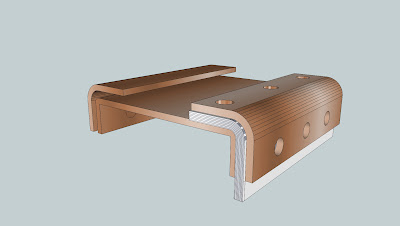
The positive tab is always folded over the negative tab.
Is this just your routine, or do you feel this adds something to the build?

potatorage said:
I purchased some solder that contains flux advertised for soldering to aluminum, but the joints are extremely difficult to make and it takes forever. Not to mention they aren't very solid either.

You mention it "takes forever" so I have this picture of you holding a 100w soldering iron against the tab for entire minutes. Heat degrades your cells. How hot are you getting the cell, when you get the tabs hot enough to solder? Is the tab material brittle after you heat it? If you flex the tab, does the solder pop right off?

Also, from your pictures, I can't tell if you only fold the tabs over once, or perform the minimum of (2) folds required to lock the cells together. With two folds to hold the balance wires, there is no need for solder them in place, just jam them into the first fold and crimp them down. Here are some pictures/instructions I posted a few years ago:

http://www.endless-sphere.com/forums/viewtopic.php?f=6&t=12461&start=60#p281360

file.php
 
I am about to assemble a 24s 6p pack for my scooter,

I have been trying to come up with a method of connecting tabs from one 6p group of cells to the next
I need a low profile connection due to lack of space.

I have considered the following;

1.5 mm copper plate which I can bend and drill as necessary, this would be clamped with bolts or self tapping screws through the tabs
tab%2520clamping%2520plates.jpg


I also thought hose clamps could be used with sections of copper/alu pipe to provide uniform clamping pressure on the tabs...
A123%2520Tab%2520clamp%2520copper%2520pipe.jpg


Or this with thick blocks of copper and the hose clamp, I would have to get these professionally cut but they would probably handle higher currents (I need 200 A continuous)
hoseclip%2520tab%2520clamp.jpg


Any suggestions welcome.
 
Can you bend it on the vertical if you have room, should be well within the pack confines anyhow.
Along the end tab. Edit opposite plane to your first photo.
 
At these levels of complexity, a tapped brass block and copper terminations like I showed a couple of pages earlier is probably the easiest way to go. It would be difficult for 1p, but for 2,3 or 4p, I think my clamping method would probably suffice. It's an extension on what Cell_Man did on my 4s,3p A123 packs.
 
999zip999 said:
A 24s6p or 144- A123 20ah cells ? 120ah.
I might take it down to 5p (100Ah) this would give enough room for built in charger.

jonescg said:
At these levels of complexity, a tapped brass block and copper terminations like I showed a couple of pages earlier is probably the easiest way to go. It would be difficult for 1p, but for 2,3 or 4p, I think my clamping method would probably suffice. It's an extension on what Cell_Man did on my 4s,3p A123 packs.
Are you referring to the PCB with slots? that did look a bit expensive for me but it would be a tidy solution.

megacycle said:
Can you bend it on the vertical if you have room, should be well within the pack confines anyhow.
Along the end tab. Edit opposite plane to your first photo.

I was originally going to go with two plates with bolts through to clamp;
2012-09-20%252014.52.50.jpg

this does give good contact and more copper is conducting, but I am a bit concerned about the stress on the top of the cells being squashed sideways, has this caused anyone else problems?
 
Wrap the 5p with palsitc wrap then tape togethere as 5p so try don't slide around. Or make a box with open ends or adjustable end so as to hold the pouches up right to work on. I made mine as 2-12s 1p. I could get my hands on them. Are you going to build 2-12s-5p I asking is it going to be split up some how ?
 
Emax%2520battery.jpg


It will look like this. Four modules, each containing 30 cells,. Each module matches the size of the SLA batteries that were originally in the scooter.
They will have steel straps to keep the cells compressed.
 
you should make it continuous from one end to the other and get rid of the metal diamond plate sides. you should not have metal case that could make contact with the terminals in an accident.

you do not wanna distort the ends of the pouches either. they need to stack flat against each other and stressing the tabs will tear them.
 
I could only fit the cells in the available space with that configuration, I would rather have used G10 instead of the diamond plate but cost prevented it so I will make sure they are well insulated.
 
I expect copper bar spacers between tabs to help take the strain off, are out of the question due to cost.
A section of your 1.5mm would be good and x2 give about the 3mm perfect spacing.
Though in saying this, the research indicates its a misconception that the whole tab area must be contacted for good throughput.
 
I was thinking of the spacer blocks between each tab but other posts seem to suggest the fewer metal to metal contacts in a joint the better.
I like Doc's clamp system here; it just wouldn't fit in the space I have.
P1000091.jpeg
 
That's true, it becomes a function of the clamping pressure here more than contact area due to thin contacting materials.
If your going to bolt the joints, use a nut/bolt/plate you can clamp the heck out of so you can squeeze the microscopic peaks together, eg15N/mm2 is recommended for copper joints.
 
Hey Guys,

Just wanted to here your thoughts on my new a123 pack

I just built it this past weekend... using the 20ah a123 cells

I decided to go with a 32s1p configuration.. nominal voltage of 105.6v & fully charged voltage of 116.8v

I used a aluminum clamp method to put the cells together, i went with 2 m5 screws for the mini clamps.. and a m3 screw for the balance tap wires...

I just to little pieces of the battery tabs for the m5 screws to fit through and clamp the tabs together tightly..

this took me a solid 2 days of work.. between drilling, taping holes, sanding the rough edges..

to give you some technical data..

i have it running on my kmx... with a full load on acceleration i go from the nominal 105.6v down to 95-94v under full load @ approx 150-160amps

i also measured the sag on 2 cells... under full load again 150-160amps.. i get 5.9v or 2.95v a cell..

Love to hear your thoughts.. i'm going to be building a very big 50s2p pack next week with the same nice neat methods.. just wanted your opinions..

pics below

Please also my testing videos on my youtube link below... 400amps load on the same building setup... i used a 4s1p pack... entire pack sagged to about 10.5v or 2.625v a cell..

thanks
-steveo
 

Attachments

  • batt 2.jpg
    batt 2.jpg
    142.6 KB · Views: 2,449
  • batt 3.JPG
    batt 3.JPG
    179 KB · Views: 2,449
there is a picture of the new 16S headway BMS on this thread that is worth the effort for those of you who need to bulk charge and use a BMS to balance but don't wanna lose an iota of power in heat to the mosfets:

http://www.endless-sphere.com/forums/viewtopic.php?f=14&t=44166

it would be money well spent if you wanna keep your pack alive for a long time. talk to jimmyD.
 
nice looking battery stevo.. I have a 20s one made the same way.. I put duct tape on the top of the battery so
anything I dropped wouldnt short something out.
 
I was testing mine at ~210amps. Had no means to monitor individual cells but 6S pack sagged from 19,5 to 17,4 that would be 0,35V per cell:
At 5:00
[youtube]BYy5YqT3oXo[/youtube]
 
Which is the best size crimp terminal to use to connect 25mm cable to the pack,they are going to be bolted to copper plate
They all seem to have minimal contact area and seem to be a bottleneck in the whole setup, these have 6,8 and10mm holes
2012-09-30%252020.28.44.jpg
 
Looks like you got the bellmouth for your stranded.
The lugs for 6&8mm should have the about the same footprint.
The 10mm should be longer and wider to allow for the larger hole.
If they are all not wider than your bus, any would do
but i would say to torque it up, 6mm could shear to easily, if you use stainless set.
I would go for at least the 8mm and put some anti seize on, could use vaseline for this, if you smear over your connection when finished.
As you probably know, but just to finish, would suggest a heavy washer close to width of lug either side of the bus.
Edit i'd suggest using a hex die to crimp? and preforming any bends in the flex prior to crimping.
 
Back
Top