• Howdy! we're looking for donations to finish custom knowledgebase software for this forum. Please see our Funding drive thread

A123 20AHr Pouch Cell Battery Build & Info Thread

Doctorbass said:
I saw a thread that Methods started that is interesting. It suggest using Fets ( solide state) instead of contactor or relay and to solve alot of existing problems we have.

http://www.endless-sphere.com/forums/viewtopic.php?f=14&t=48166

The battery is finished and i am at the point where i need to connect the Signalab 16s BMS to the battery but it's a stock 40A bms. the first idea i had was to use 4 car relay with coil in serie to get an equivalent 48V coul that would be driven by the BMS output and have the contact in parallel. I would het about 80A x 4 = 320A max and have 160mA of current to drive the relay that wold also be activated with a 12V relay that conect to the Zero 12V system so once the zero is ON, the relay let the 48V out of the BMS to go to the relay coil and activate them to conduct up to 320A. this desing is simple but will draw 170mAh every hour... for nothing... and these 1 cu inch car relay just dont enter in the battery case i designed... :(

Then i thought abot using my EV-200 that would be driven by a 48V to 12V dc-dc where the 48V is from the BMS output... but again the contactor is big and draw 1.9W for nothing... i could also add a 12v relay in serie that would be active only when the zero is ON, but it add some connections between the battery and the motorcycle.. and also the EV-200 is too big.. i would need to install it out of the battery wich is not esthetic.

Then i thought about adding some 4110 mosfet to the signalab bms and use it as is but with more parallel mosfet... i remember that i was able to drive like 20A continuous with minimal heat sink at 58V for only one mosfet...! so for 300A+ i would need 15 of them... and if my controller have regen i woul need to double that !

OK.. wait a minute... 300A is for burst and the average is more like 50-60A on my Zero.. at least... this is what i have recorded with my Cycle analyst... so this mean i could just install like 10 of them for having 100A cont and 400A burst? safely? Hmm ... will see with the update on his thread.

Doc

Doc, what about bypassing BMS fets all together? Controller must have shutoff, why not use that and have 1200A burst :)
 
2 or 3W for the hold in current for the coil,l not a lot doc.
Should be able to surge the contactor to twice its normal rating for a few secs.
 
agniusm said:
Doc, what about bypassing BMS fets all together? Controller must have shutoff, why not use that and have 1200A burst :)

I dont want to ruin my great battery :wink: I want to keep the protectoin at the cell level.

I fianlly succeded to modify the signalab BMS FEt with the 4110 and have 2 fet for charging instead of one. I tested at 20A and they barely get warm ( about 35 celsius) so i guess i can charge at 40A no prob ( 1C)

for the discharge i will go with the EV200 contactor. driven by the 12v DC-DC. the contactor + dc-dc consume 2.9W wich is acceptable during the use.

Doc
 
Ypedal said:
you absolutely need a pre-charge circuit with those EV200 contactors, i've had one spot weld itself closed circuit..... fyi.. but i'm sure you know that already.


Ypedal, i know thanks.. but surprizingly there is NO need of precahrge on that project :wink:

The controller is always at the Vbatt since it is permanently connected to the controller in the zero.. so once i will turn the key ON, the only voltage the contactor will have to see is the V diff between the A123 battery i'm adding and the actual Zero battery wich will be under a volt :wink:

Both battery will be in parallel but only connected together when the key is ON... and the charging current will be in parallel but protected with two schotky diodes to avoid one o fthe pack to overcharge the other when the HVC is reached on one of those.

Doc
 
Tonight i measured the energy of my 16s2p A123 for my zero battery upgrade.

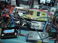
Here are the results with the battery top balanced at 3.65V with the help of the BC168 great tool:

CONTINUOUS DISCHASRGE AT 1C:
Total capacity: 37.32Ah (at 1C) That's exactly what i have measured at 5.5C discharge ( 100A) wich is 18.66Ah per cell average
Total energy: 1879Wh ( at 1C)
LVC was 2.1V cut

BMS is the Signalab V2.5 that i modified with copper heatsink and 5x 4110 Fets ( 3 for the load and 2 for the charge) From now the load will only be the dc-dc and EV200 contactor that will drive ULTRA HIGH CURRENT for the BMS.

After that i began to charge it with my meanwell 1500W that output 37A max and the two charge mosfet only got a little warm... I measured 47 celsius wich is encouraging. The turnigy 10AWG is really doing a great job at that current!
 

Attachments

  • 20130309_184151_800x600.jpg
    20130309_184151_800x600.jpg
    115.4 KB · Views: 4,209
  • 20130309_184223_800x600.jpg
    20130309_184223_800x600.jpg
    88.8 KB · Views: 4,209
  • 20130309_184335_800x600.jpg
    20130309_184335_800x600.jpg
    74.5 KB · Views: 4,209
Hi Doc. Very nice. I also have that BC168. Does it measure discharged capacity? I used it once but have not checked if it can do that. i have used 4 of these A123 cells for a car starter battery this winter up to -20 and i assume charging was happening at this temp. Want to see the effect on cells charging at freezing temps.
 
agniusm said:
Hi Doc. Very nice. I also have that BC168. Does it measure discharged capacity? Want to see the effect on cells charging at freezing temps.

I dont know i only tested teh cahrge capacity. will try later for teh discharge.

A123 system have some document about performances on cold temp and as any lithium ion cells if you push too much current into the cell at low temp, it will corrode the anode and cathode inside.

But A123 specified that the charging voltage can be up to 4.2V max at temp below zero to compensate for the high interna resisance and have some current going to the cell. Well at least that's what they specified for the 18650 1.1Ah round cell in a confidential pdf document ( i attached couples of these that i saved before they remove them from online acces :wink:

Take a look :D

Doc
 

Attachments

  • ANR18650M1%20Confidential.pdf
    226.5 KB · Views: 149
  • A123 M1 spec.pdf
    348.8 KB · Views: 114
  • AMP20M1HD-A.pdf
    146.2 KB · Views: 124
My 24s as two 12s packs charged on a 1420 no bms running a 2810 at 30 amps limted by a C.A.. I get 17ah and still balanced pretty well. I triied 17.5ah and it started to unbalance badly and wouldn't try again. So I'm happy with the pack at 17ah.
 
I also got about 18 aH when I tested the D/C but we rarely use more thatn 12-13. I do notice some sag even at 25 amps going up a hill, though. Of course my trike and me weigh about 150-160 kilos.
otherDoc
 
I do have hills as sometimes or most I just go around and take the littler longer hill. All batteries sag. But after 9ah I could feel it in my seat but after 14ah you know it. And no problem. Meaning you can feel when the battery dosn't like it any more 16.5ah and just better go home. Because of having 20ah cells you get a understanding. Not saying I would run without a C.A.
I'm going to get a alarm for which I guess might be the weak cell (s) but the weak cell sometimes moves and has been lately. ? Weird.
 
for kicks i tested some of my osn cells with a 0.1ohmite 300 watt resistor in cold water + watt meter
charged cell upto 3.6 ( let it sit 1 hr)
resting voltage 3.4v
i did a quick load test - resting voltage was 3.35 and dropped to 3.2 after 10 seconds under 30amp load
after about a minute my voltage dropped to 3.17 and sat there a bit -
i ran a constant load of 29amps
9ah i was down to 3.11
12ah - 3.09v
3v- 16.22ah
i cut the test at 2.7v getting 18.17AH (cell was cool)
all in all no crazy sag- not bad
 

Attachments

  • not.jpg
    not.jpg
    22.7 KB · Views: 3,905
My 24s 20ah Pack about a year old. Charged with a hyperion 1420 to 3.59v. everytime. So about 82v off the charger. I got 18.08ah on my C.A. 1446.6 w/hrs, 72.0 volt cutoff, 39.0wh/mi. with a 2810 at 30 amps. for 35.73 miles. lot's of rolling costal hills.
1. 3.06v 13. 3.10v
2. 3.06v 14. 3.17v
3. 3.02v 15. 3.07v
4. 3.09v 16. 3.01v
5. 3.09v 17. 2.97v
6. 3.09v 18. 2.98v
7. 3.11v 19. 3.00v
8. 3.04v 20. 3.09v
9. 3.10v 21. 3.06v
10.3.10v 22. 3.07v
11.3.11v 23. 3.16v
12.3.08v 24. 3.06v
Now this was taken after I could get the battery unhooked and the fluke on the 6s cheater block and probe the 24 pins. So I could have gone down as far as 2.7v under load ? What maybe more ? So pretty happy with it and have run it with a 3525 at 60 amps no problem but the motor got warm. It still weighs alot and thing I might go to 16s and use more amps ? But would buy more cells.
 
999zip999 said:
What maybe more ? So pretty happy with it and have run it with a 3525 at 60 amps no problem but the motor got warm. It still weighs alot and thing I might go to 16s and use more amps ? But would buy more cells.
My experience is that these cells hold their voltage well, so knowing you've exceeding some draw-down limit, like down to 20% of capacity, is a mater of monitoring amp-hours, with something like a watt's up meter or cycle analyst. The question remains, however, how much capacity does a cell retain as it ages? Get too close to a draw-down and there's the possibility of permanently damaging a cell. I believe we'd all like to get 2000+ cycles out of our packs. So, what to factor into the capacity equation as a pack ages?

Also, where are you going to source new AMP20 cells?
 
Arkmundi I just run it down to 12ah's this was a test. After I run a couple of cycles at 60amps but the 3525 got to hot, I think it could have been a scruffed phase wire. I would get the cells from Nancy at OSN. But looking at the 32157 7-8ah cells with screw tops as 2p. I just havn't heard any reveiws. Plus a little pricey at 16.50 ea.
 
I'm new to this forum but I have been reading a lot about battery pack assembly for these cells. I'm planning to build a 3p22s pack split into 2 11s packs. I plan to use this in a racing application so a pretty decent level of stress. I stole a lot of how I designed these packs from Plasma Boys pack along with a few of my own ideas. I wanted to make it so that I could easily replace a 3p section of cells in case of bad cells and just for easy maintenance. Each 3p section has an aluminum plate on each side to act as a heat sink and used to put even compression force over the surface of the cells from the nylon shipping straps. Between all of the components of the 3p "module" there will be double sided tape and a 1mm ABS plastic spacer. The tabs of the cells will be bend and trimmed to length so that the copper compression plate can put even pressure on each tab.

Any and all advice you can give me would be great. I'm looking to the people that are much smarter than me when it comes to batteries and this is the place to find those people. Don't let me down! :D Thanks ahead of time!
 

Attachments

  • Folding Sub Assembly.pdf
    281.7 KB · Views: 156
  • Folding Full Pack.pdf
    317.4 KB · Views: 157
  • Folding Full Pack-1.pdf
    393.3 KB · Views: 125
Nice pack design. What amps would you be needing ? Don't roll the dice on Victpower as their shit is looking like junk now. Get a couple of spares. BMS or no bms ? How you going to charge ?
 
Yes, it always does look nice on renderings but have you thought actually building it? I see a loot of renderings where people dream sitting and drawing something without thinking about actually building it and most of the time it ends up, well a digital sketch.
Have you thought how much it will cost you to produce all the bits and bobs? Sometimes it works out cheaper and better to buy ready made product than produce it yourself.
I would ask few questions first about the design. How do you bold the copper bars? Heat sinking does little from what i read. The way A123 was doing their modules is each cell encased in aluminium sheet(.5mm) which is folded at the edge. This edge then was covered in thermal compound to transfer heat to battery case with integrated liquid cooling, Fisker car.
I dont see you pulling 20C from these cells without proper liquid thermal management implemented.
I see it as costly design. You'd be better getting something from Enerdel, eg. four modules MP320-049
in 2S2P fashion you would have something close to what you need: 64AH, 320A continues, 560A 10s, 64kg, only slightly higher voltage at 24S plus some 3 years warranty, genuine supply of spare cells, US based and with relationship of todays A123 owner - Wanxiang group.
 
999zip999 said:
Nice pack design. What amps would you be needing ? Don't roll the dice on Victpower as their shit is looking like junk now. Get a couple of spares. BMS or no bms ? How you going to charge ?

Thank you! Yes to the BMS, it's an Orion. I believe that we drew 100A continuous with a few millisecond spikes of 650A on the old thundersags. I'm finding out about the charger now.

agniusm said:
Yes, it always does look nice on renderings but have you thought actually building it? I see a loot of renderings where people dream sitting and drawing something without thinking about actually building it and most of the time it ends up, well a digital sketch.
Have you thought how much it will cost you to produce all the bits and bobs? Sometimes it works out cheaper and better to buy ready made product than produce it yourself.
I would ask few questions first about the design. How do you bold the copper bars? Heat sinking does little from what i read. The way A123 was doing their modules is each cell encased in aluminium sheet(.5mm) which is folded at the edge. This edge then was covered in thermal compound to transfer heat to battery case with integrated liquid cooling, Fisker car.
I dont see you pulling 20C from these cells without proper liquid thermal management implemented.
I see it as costly design. You'd be better getting something from Enerdel, eg. four modules MP320-049
in 2S2P fashion you would have something close to what you need: 64AH, 320A continues, 560A 10s, 64kg, only slightly higher voltage at 24S plus some 3 years warranty, genuine supply of spare cells, US based and with relationship of todays A123 owner - Wanxiang group.

Getting the parts that I specified to be 3D printed is free for me, so there is no cost there. The copper bus bars are held down with 4 screws per side, so 8 per bus bar to help maintain a solid amount of pressure on the tabs. I also want to nickel plate the copper bus bars. I'm not too concerned about heat sinking, but I thought I would just get some opinions from people. Either way I need to aluminum plates on the end for compression purposes.

The rules for this race are very specific. We are limited to an instantaneous amperage draw and a total amount of power on board for the race. Last year we had 60Ah on board so we should be fine again with 60Ah. Weight is another key area. If anyone has suggestions on materials or anything that would help make things lighter that would be great too. I know that right now the case is super heavy the way I have it designed but I'm not sure of any other way to do it without spending stupid amounts of money. It is 1/2" poly-carbonate so it is nice and strong.
 
Finally making some progress with my 7.2 KWh pack build.(72v 100Ah)

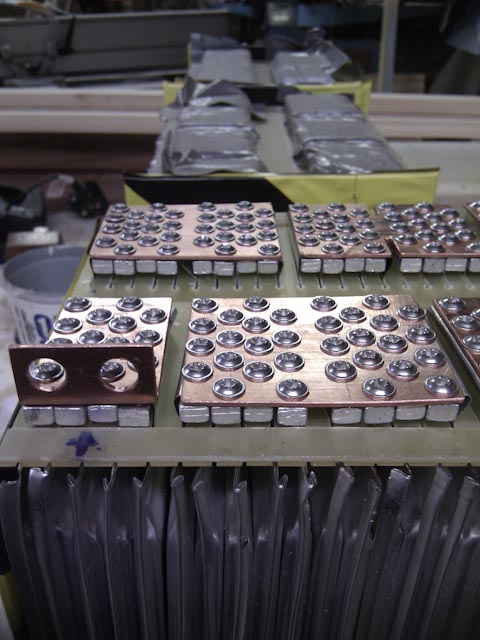
Each module is 6S 5P, there are 4 modules in total to replace the SLA's in my scoot.http://endless-sphere.com/forums/viewtopic.php?f=10&t=38617

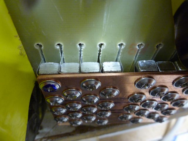
The cell tabs poke through slots in a 1.5mm GRP sheet.

The tabs are clamped underneath the copper plates by 5x7mm aluminium bars, each bar is drilled and tapped for 4, 6 gauge, stainless, self tapping screws, all torqued up and threadlocked.

I have narrowed the middle copper plate on each module to create a weak spot in case of a major short,(there's no room for a suitable fuse)

I'm hoping this will handle 200A continuous.

Can anyone let me know the cross section of copper I need that will melt at around 500A? I'm using 1.5mm copper sheet

20130514-P1080476.jpg


20130514-P1080479.jpg


20130526-IMG_20130526_174559.jpg


20130526-IMG_20130526_174715.jpg
 
Hi Flexy.
Good to see your build 8)
I think you really need to think this through at this level of fault current.
That gap being used as a fuse link might possibly sustain an arc for longer than recommended or continuoulsy :shock: which could be catastrophic, it would at least heat up the surrounding copper damaging your plates.
Littlelfuse do thin ANL fuses or fuse strips, it could be mounted sideways across the gap using short peices of your copper strips, from your blocks http://www.littelfuse.com/Industries/Passenger%20Car%20and%20Commercial%20Vehicle/Bolt%20Down%20Fuses.aspx, you can see the size of the fuseable section is a lot longer for 80V than 32V strip.
Your terminal PSC will be about 5Pxcell PSC = 2.5kA. I think the ANL type are 80Vdc @6kA but would have to check the kA rating ive heard some are 1kA which could leave a mess. You could make your own fuse holder if it was a strip fuse, but i'm sure a lot would be slimmer than your block height.
Sorry my phone internet browser has blown a fuse :wink: otherwiae i would of posted some pics, but it dies when i try to save them :?
 
megacycle said:
Hi Flexy.
Good to see your build 8)
I think you really need to think this through at this level of fault current.
That gap being used as a fuse link might possibly sustain an arc for longer than recommended or continuoulsy :shock: which could be catastrophic, it would at least heat up the surrounding copper damaging your plates.
Littlelfuse do thin ANL fuses or fuse strips, it could be mounted sideways across the gap using short peices of your copper strips, from your blocks http://www.littelfuse.com/Industries/Passenger%20Car%20and%20Commercial%20Vehicle/Bolt%20Down%20Fuses.aspx, you can see the size of the fuseable section is a lot longer for 80V than 32V strip.
Your terminal PSC will be about 5Pxcell PSC = 2.5kA. I think the ANL type are 80Vdc @6kA but would have to check the kA rating ive heard some are 1kA which could leave a mess. You could make your own fuse holder if it was a strip fuse, but i'm sure a lot would be slimmer than your block height.
Sorry my phone internet browser has blown a fuse :wink: otherwiae i would of posted some pics, but it dies when i try to save them :?

Thanks megacycle, those 80V fuse strips look ideal, it gives me more ability to keep it low profile, I'll have work out a way to fit them.
 
No worries anytime :D .
Your block width with the gap must be about 9x7-8mm, approx 70mm ish.
I was envisaging that ANL strip or fuse would be about that long, so if 2 peices of your copper plate about 25mm wide were bolted at right angle onto your plates, the fuseable section would have about 20mm'ish of a gap to sit across.
Sorry still having trouble with downloads, but looks about right, you need a decent gap to clear the arc and obviously some kind of cover to contain it, just a peice of thin formica for a base and a peice of perspex on top, to see if it's blown.
Cheers.
 
Back
Top