999zip999
100 TW
I mean I don't understand the whole compression thing. Where did you get the cells and which ones.
 .
.wb9k said:Coming in late here, and I haven't read the whole thread, but I'm seeing questions on compression, a mysterious topic to many.
Shoot for 10-12 psi evenly distributed across the flat surfaces of all cells. You want light compression.
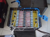
Some nice looking packs on the last couple pages here (and maybe elsewhere), but I would not pile up cells right on top of one another with no material in between. At the very least this will likely lead to hot spots in the pack and possible premature death for the innermost cells. I see some mention of current flowing through the foil pouch, but this should not happen normally. That pouch is supposed to be isolated from the cell electrically, in contrast to our cylindrical cells which have the cans strapped to the cathode. However, breaching the pouch insulation is not too difficult, especially in a cell that has been removed from a module and subjected to unknown handling procedures by God-knows-who. Additionally, any debris that may get in between the cells can become an issue when cells expand. Our modules have thin foam sheets or heat sinks between each cell. These together mitigate both potential issues.
dh
. Sophisticated gear attatched to them, but noone up to now has particularly provided any technical input on cell mechanics. It would be good to have find some 2nd order info from the manafacturers, saying this is exactly what you have and need to do with them and this is how you would kill them. . Sophisticated gear attatched to them, but noone up to now has particularly provided any technical input on cell mechanics. It would be good to have find some 2nd order info from the manafacturers, saying this is exactly what you have and need to do with them and this is how you would kill them.

Mr Ed said:steelmesh said:I am trying to find a supplier for these AMP20 cells. I was looking at the lot of 40 pouches from "Shenzhen Victpower Technology" for $780 shipped: http://www.aliexpress.com/item/free-shipping-No-logo-full-tab-A123-20Ah-system-3-2v-lifepo4-battery-cell/708063093.html
I've been reading the okay and bad on this supplier, I will end up needing 30 of these cells for my pack. If 10 pouches were junk, that is about $26 per good cell. This is all speculation, how is the market today for the AMP20s?
I'm currently in an Aliexpress dispute with them right now over an order of 32 cells that are nothing like the previous samples they supplied. While they were fully helpful discussing the deal by email, they have turned decidedly cold with their latest response despite my suggestions of paying for return shipping so it's not like they are even losing out financially. The official dispute process takes 3 days so I don't want to say any more here until I have a definite ruling from Aliexpress. If I lose out then I'll be chalking it up as as one of my harder lessons in life and will probably put them up for sale here for half price or something (full details/disclosure of course - I HATE SCAMMERS!).
If this is not the right thread, please let me know. It was initially about pack construction but seems to have morphed somewhat recently into AMP20 suppliers. I've enjoyed reading it, regardless, and am planning a 180s1p Drutledge-style high power pack split into 3 or 4 sections (with my own tweaks/improvements of course - after all, I am an engineer!).
Edward
bigmoose said:wbpk just to be clear since the cells are approximately 6.4 in x 8.9 inches at 10 psi we want a compressive force on the stack of about 570 lbs. Is that correct?
Doctorbass said:April said:Hi Doc,
This is April or Nancy from OSN Power.
About the kit, I reported your worries to our technicians.
For the kit, only the general postive and negative end carry the high current, other matal plates mainly to create the clamping pressure, so no worry about the soften of the plastic plates.
And we have tested the clamping pressure of the kit, there is no problem.
The material of the kit is a kind of special epoxy resin, not common plastic, and the studs and screws are copper.
On the general postive and negative end, there are two special matal bars sandwiched together, which is used for high current.
By the way, we are now developping a new special matal bar on the general postive and negative end to update the kit especially for high current.
Hi April,
I understand your explanations but the problem is that the flat bar you use and the only two screw with one on each end make the flat bar to bend and not have the pressure to all the width of the surface.
I made a drawing to explain what i mean. Please consider that you might not see the bending wby eyes but in high electrical current, a simple variation of pressure mean alot of diference and your proposed desing can not guaranty that pressure along all the width of the cell tab
bigmoose said:Thank you wb9k, your detailed information is priceless! It is filling many of the voids we had in the engineering of the battery pack.
yokneamcity said:I also encountered this problem. I'm make a battery for Vectrix scooter.
Added another screw in the middle of each plate.
But there is another problem, several packages were swollen. Packages bought from OSN company.