A123 20AHr Pouch Cell Battery Build & Info Thread

In the most general terms, you can't solder aluminium. You can make a mess which doesn't move when you tug on the wire, but it's only being held there by friction.

There are means to bond aluminium with more aluminium, but the process will probably ruin your cell given the heat you need to pump into it.

Spot-welding copper to aluminium is currently the only way to do it. Or just clamp it nice and tight like others have.
 
arkmundi said:
Agniusm's kit works great. If not the kit, at least look at the construction methods used and attempt to copy them. Uses the clamp method - a hex bolt and bar. This method is superior in that it also enables deconstruction, as in when a cell needs replacing.

Definately +1 for agniusm's kits! Superior quality and farily foolproof assembly. I have 2x6S as a split 12S pack and it is going on my trike this week. Will show fotos.
otherDoc
 
I have thought about Alu solder but I think you will burn through the tab, it will get too hot.

Isn't there something like a glue that can replace solder ?
http://www.thinkgeek.com/product/b70c/

The nuts and bolts idea is much stronger and better but maybe in combination with this kind of glue to make even better/ more contact ?
 
Bazaki said:
I have thought about Alu solder but I think you will burn through the tab, it will get too hot.
Isn't there something like a glue that can replace solder ?
http://www.thinkgeek.com/product/b70c/

The nuts and bolts idea is much stronger and better but maybe in combination with this kind of glue to make even better/ more contact ?
Yes, there is conductive epoxy that can work in the place of solder. But you really need to avoid anything so permanent. Solder can at least be removed if needed. These cells for various reasons can fail, in which case you'll want to replace just those cells. An approach which allows both easy assembly and dis-assembly is whats required. Only a clamping approach meets that requirement. Instead of mulling over such options as "glue" you have been advised as to the best approach by those who have built and are using these cells. Best.
 
I prefer something that can be undone also, but maybe it can be helpful for a complete module like 7s3p or 28s3p.

I ordered a 28s 3p module and as seen on some pictures these modules are laser welded and are hard to replace, I wonder what happen if dremel them out, I hope there will be enough Tab left to clamp something, if not maybe the glue can help. But for 1000A the glue is probably not enough.
 
Potatorage, fresh cable cut to tab width and wrap a few strands around the cable end just to keep it together and wrap the tab around the cable end, not soldered and clamp the heck out of it with a couple of copper clamps like zipman's, drilling through a few M5's or similar.
Without an end plates, or a box to keep it together, the tabs and cells are liable to mechanical damage.
Can't secure that cable without somekind of structure.
 
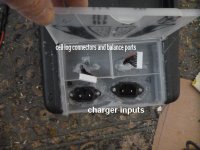
Heres some pics of a 48v a123 20ah pack I made for a mate, tabs are crimped together with wood spacers, box is from bunnings, just a plastic tool box,
pretty much water proof, used silicon to water proof it, seems to work quite well, only used for standard ebike at about 20amp current draw.
Pack is isolated into two 24v packs for charging, two chargers used.
Charging system uses one turnigy ( used for balancing also) and one hobbyking charger ( not used for balancing cause it actually unbalances the cells but ok just for charging).
ebatt1.jpg
ebatt2.jpg
View attachment 2
View attachment 1
ebatt5.jpg
 
So the mate is still a mate as in still alive.
 
I finally was able to order the circuit board and all the nuts and terminals from Nancy at OSN Power.

I'll post pix when they arrive.

image.jpgj
 
That's so nice and KISS.
Seperate kit parts, excellent.
Looks easily fabricated.
$60 for that many peices, sounds cheaper than trying to produce similar.
What is the current rating? What cables were supplied?
 
I'll update everyone when it arrives with photos and a quick review. Stay tuned!
 
ambroseliao said:
I finally was able to order the circuit board and all the wires, nuts and terminals from Nancy at OSN Power.

The total $ for 2 kits: enough to assemble 2 12S 36V nominal packs was $60 including shipping. I'll post pix when they arrive.

Nice Ambrose, I look forward to seeing your progress, I might give those boards a shot. Do you know if they had any parallel-cell versions?

-JD
 
From looking at the picture, it looks like it's simply slots cut out of a plain fiberglass board so there's nothing stopping you from using them in a parallel configuration and bolting them together rather than putting them in series.

I may be wrong of course. I'll let you know when they arrive which is hopefully in a week or two.
 
megacycle,thank you for the short tab testing im now more confident in my shortys.

I followed your suggestion and made the connections as close as possible to the tab base.
Two brass plates whith three M4 * 10mm sqewre, nut and spring washer, do think thredlock will be necessary ?


2012-11-29033147.jpg


2012-11-29033212.jpg


All pack builders beware, these cells are extremely powerful, I burned my hand when accidentally shorted two cells

IMG-20121114-WA0002.jpg


Michael
 
Nice and tight looking 8) .That's a novel way of providing strain relief on the balance cabling too 8)
Crap :shock: :shock: major KF there, sorry to hear that, you ok?

Yeh no threadlock that's what the spring washer does, though normally there'd be a washer under the spring, should be ok though.
Have you got insulation going in between those threads and neighbouring plate?
There a touch long, could just cap the thread ends, buzzing them of might be a pain now.

Brass isn't the best heatsink going, but that's not a drama, might still be good pulling big numbers for dissipation. Are you doing a load test?
 
I hope people can read this and get enough detail. Been tested to 320amps, 8AWG wire gets hotter than the tabs. I have built several packs like this in 16S with bms, 20S no bms just charge with icharger by breaking pack in 2, and 24S with "emissions free" high amp bms all working excellent. These are great cells!
 

Attachments

  • P8230078.jpg
    P8230078.jpg
    64.4 KB · Views: 3,327
  • P8260089.jpg
    P8260089.jpg
    64 KB · Views: 3,327
What are you going to put between the clamped taps so they don't bend over and touch each other and short ? I mean look how Ping builds his packs. Or the Osn battery in this thread threading the tabs thru a broad first and Ping puts a weather strip under that. Or slip some shrink wrap like Oatnet build for protection.
 
I cut some 10mm vinyl tube to length and then slit it down the side and they slide on and offer good insulation for cheap.
Zappy
 

Attachments

  • P1250051.jpg
    P1250051.jpg
    82.8 KB · Views: 3,499
While its very neat, could just do what Michael did and just two plates, no fold, less work.
Nylocks, how do they go with heat, they ok? for the application.
 
The reason i folded the copper was to increase the tabs joint cross section. The fold has a cross sectional area of 31.5square mm of copper or close to the equivalent of an extra 2AWG wire. Relying on the stainless steel bolts to carry the current across between the 2 clamp plates which has approximately 40 times the resistance and a smaller cross section than the folded copper tab. So i think this folded setup may run cooler but only under extreme amp draw for, most bikes it would never be a problem. Silver or zinc conductive grease also helps and also reduces any electrolysis problems between the copper aluminum tabs in the future. The folds don't take very long to make, maybe an hour or so.
Zappy
 
The bolts won't be carrying current between the tabs, the tabs are sandwiched, the tabs pass current.

Increasing the csa of the join by large overlaps doesn't much improve the conductivity of a compressed joint.

Copper clamp probably be a good heatsink though, for big amps, smear of thermal paste between tab and clamp might help too, wouldn't be cleaning the copper with a file then, polish if oxidised.
Would have to leave the balance wire area without paste though, to pass balance currents.

Putting conductive grease in between a tab sandwich like this and likely increase its resistance.
Actually i'd like to check this urban myth soon, true or mythbusted.
I might have some grease around somewhere. I'll use 2 sections of sandwiched bus and for same current do a mV drop test.
 
Nice and tight looking .That's a novel way of providing strain relief on the balance cabling too
Crap major KF there, sorry to hear that, you ok?

Yeh no threadlock that's what the spring washer does, though normally there'd be a washer under the spring, should be ok though.
Have you got insulation going in between those threads and neighbouring plate?
There a touch long, could just cap the thread ends, buzzing them of might be a pain now.

Brass isn't the best heatsink going, but that's not a drama, might still be good pulling big numbers for dissipation. Are you doing a load test?


Thanks megacycle, yeah im OK suffer just minor burn. There will be insulation between the tabs, some plastic sheet i ges.

The pack designed for 1000W motor so 30A (=1.5c) at max, I'm not concerned about heat sinking.

I asked this question in the hyperion 1420i thread no answer there, I'm using the 1420i grate machine but discharge rated at 80W max,
so 2A load for fully charged 12s pack. I'm looking for some cheap way to increase the discharge load of the charger. My idea is to
connect high power resistor between the pack and the charger, and set the charge to discharge mode, will it work ?


Michael
 
Back
Top