etriker
100 kW
sendler2112 said:No mention of the USA tab welding issue?
It says they hid that from investors ?
sendler2112 said:No mention of the USA tab welding issue?
countermeasure said:Guys.
I just dug through a lawsuit file against A123, on the AMP20 pouch cells. Downloaded the original document from stanford.edu.
It's 66 pages long. Here is my take away:
1. The original AMP20 is made in Korea. The Korean cells seemed OK. The US operation was setup later with Korean process.
2. Majority of the AMP20 cells made in US did not meet the quality control spec. Using a US AMP20 cell is like playing the Russian roulette.
3. A123 knew they had a quality control problem and covered it up.
4. The US made AMP20 cells may have bad electrode coating.

Doctorbass said:bigmoose said:I snagged one of the battery termination kits that ambroseliao purchased and described a couple of pages back from Nancy at OSN Power. I find it well made and would have used the same words he did in describing it. Using his picture, it is the same kit:

I bought it because my scratch design was 90% similar to theirs in form and function, and it sure saved a lot of work on the milling machine!
What I will add is Nancy from OSN was just a great person to deal with. Her english is 100% and I found her extremely helpful and responsive. Kit came a little over a week from my purchase date. All in all an A++ transaction for me.
Bigmoose, These kit look interesting due to the easy and fast way to assemble the pouches. Do you agree with me that it would be only recommanded to use with low to medium power ?
There is two importants points i think that make them more risky for high amp ( let say 50+ amp)
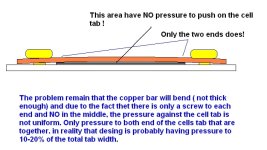
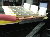
First , I believe that the pressure uniformity on the tab width is weak. The two screw at each end will make the conductive top bar to bend and not have the same pressure on the center as the pressure on the sides near the screw. There is no screw to push to the cell tab to all their width. so the contact is not made on 100% of the tab width and i think it is way lower than what it look like. if you torque more the screw, it might get worst.
And, in electrical engineering, having high current conductor in sandwich between plastic and metal is not a good idea due to the possibility that the plastic soften depending on the temperature, reducing the pressure on the cell tab and increasing the contact resistance. And as the plastic soften, as the contact resistance goes higher and that loop could result in hot spot or melt plastic and even create a fire if the current is sustained. cheap chineese plastic are not fireproof i think. That kind of sandwich was what few years ago have made one of the Hymotion plug-in hybrid Prius battery to burn to the ground due to bad electrical contact desing with a screw torque between metal conductor and plastic battery case.
That’s why I preferred to buy some of the kit that Agniusm made wich are excellent to me but are a bit more expensive and require more assembly time, but I think it worth anyway.
The agniusm kits are not using plastic but FR4 ( pcb fiberglass material) with does not soften at the temp range the battery tab can reach, it is more hard material. And also the sandwich conections is made with two aluminum bar and 3 screw that spread perfectly the pressure along the cell tab width wich guaranty the electrical resistance to keep low and stable.
What do you think?
Doc
April said:Hi Doc,
This is April or Nancy from OSN Power.
About the kit, I reported your worries to our technicians.
For the kit, only the general postive and negative end carry the high current, other matal plates mainly to create the clamping pressure, so no worry about the soften of the plastic plates.
And we have tested the clamping pressure of the kit, there is no problem.
The material of the kit is a kind of special epoxy resin, not common plastic, and the studs and screws are copper.
On the general postive and negative end, there are two special matal bars sandwiched together, which is used for high current.
By the way, we are now developping a new special matal bar on the general postive and negative end to update the kit especially for high current.
Doctorbass said:countermeasure said:Guys.
I just dug through a lawsuit file against A123, on the AMP20 pouch cells. Downloaded the original document from stanford.edu.
It's 66 pages long. Here is my take away:
1. The original AMP20 is made in Korea. The Korean cells seemed OK. The US operation was setup later with Korean process.
2. Majority of the AMP20 cells made in US did not meet the quality control spec. Using a US AMP20 cell is like playing the Russian roulette.
3. A123 knew they had a quality control problem and covered it up.
4. The US made AMP20 cells may have bad electrode coating.
it's good to know...
But from all the 180 cells i tested individually, all 180 was with in 2% of the original specs and have a exellent RI and capacity uniformity over all teh cells.... and they are from USA and boughht from Victpower.
I think that if they pass these Doc test it worth playing russian roulette! :wink:
Doc
bigmoose said:Doc, sorry I didn't check back in and missed your comment/question. Yes, I agree that the stock OSN kit is only good for low power...like you said something around 50/60 ish amps, and I fully agree with the metal cap strips bending as shown in your drawing. For high power, like you run, there should be a steel insert under the tabs, and one over the tabs with a machined in bowed surface (convex surface) on both surfaces touching the tabs for proper compression. I would put 0.007 to 0.010 inches ~0.2mm of "bow" on each part and tailor the thickness so that it goes flat under the compression of the screws. The clamps do not need to be made of highly conductive material.
bigmoose said:Just for clarity, I was commenting on the OSN cell clamping "kit" that has been sold, not the cells themselves.
I just finished reading the court documents against the A123 USA production for Fisker and the allegations are quite damming. I am glad that I am storing my A123 pouches in a covered trailer "out back" of the house.
That said, the issues seem to be in two major areas, moisture contamination and the defective sonic welding machine/procedure. I will throw an opinion out that the defective sonic weld should be apparent with measurement of the cell's internal resistance. The moisture issue may not be externally measurable until the cell degrades early or goes "poof".
I am really upset that an American company allegedly did this, especially one that got tons of government grant money to develop these cells over the years. If the allegations are correct, these million dollar a year executives should be stripped financially and be put behind bars...they knoweth what they dooith.
Doctorbass said:DOCTORBASS Zero Motorcycle 2kWh battery upgrade using A123 pouchs
Yes it's finally time for me to begin that great project for extanding the range of my Zero motorcycle 2011 ! The idea is to begin by adding a 2kWh pack made of 16s2p A123 pouchs and to quick install it on my zero OR on my KMX trike for about 100km range.. or on the Zero for about 40km more range.
The goal is to have a battery pack that is strong and will protect cells from hard vibration, puffing, puncture, cold etc.... adn that will be as strong as if it would be welded( I used flat 8-32 screw and Dp-420 off white epoxy)
-Testing all 34 A123 pouches cells in RI and Capacity at medium rate 34 cells tested. CHECK
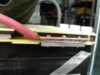
-Preparing all cells for the Agniusm kit: CHECK
-Assembling all cells in the AGNIUSM kit: CHECK
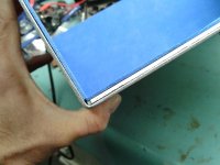
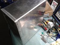
-Building the aluminum box to be strong, water tight and welding free: CHECK
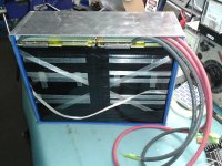
-Preparing the 6 AWG cables for connnectin to cells: CHECK
-Installing the Signalab 16s BMS and upgrading it for 400A: PENDING
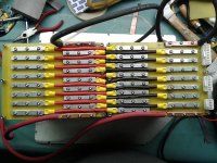
Here is some pictures for you guys :wink:
Doc
etriker said:Hybrid approaches with two batteries in parallel
Parallel a different battery chem with A123 cells to allow each battery to play to its strengths in the system ?
steveo said:Doctorbass said:DOCTORBASS Zero Motorcycle 2kWh battery upgrade using A123 pouchs
Yes it's finally time for me to begin that great project for extanding the range of my Zero motorcycle 2011 ! The idea is to begin by adding a 2kWh pack made of 16s2p A123 pouchs and to quick install it on my zero OR on my KMX trike for about 100km range.. or on the Zero for about 40km more range.
The goal is to have a battery pack that is strong and will protect cells from hard vibration, puffing, puncture, cold etc.... adn that will be as strong as if it would be welded( I used flat 8-32 screw and Dp-420 off white epoxy
-Testing all 34 A123 pouches cells in RI and Capacity at medium rate 34 cells tested. CHECK
-Preparing all cells for the Agniusm kit: CHECK
-Assembling all cells in the AGNIUSM kit: CHECK
-Building the aluminum box to be strong, water tight and welding free: CHECK
-Preparing the 6 AWG cables for connnectin to cells: CHECK
-Installing the Signalab 16s BMS and upgrading it for 400A: PENDING
Here is some pictures for you guys :wink:
Doc
Hey Doc
Can you post a discharge test?
maybe at 100 amps & 200amps..
would like to see your voltage sag...
-steveo
dnmun said:beautiful work doc. simple and elegant.
i had previously recommended a thicker clamping bar on the OSN, but for those who have a set to play with can you tell if it is possible to drill a hole through the assembled clamp and tab and put a screw through with a nut and flat washer on the backside to clamp in the middle to distribute the clamping force?
or maybe drill and use a pop rivet with a washer on the underside to capture the nipple sticking through and have a wide enuff seat to clamp the middle of that bar? or add a steel bar on top of the copper clamping bar?
countermeasure said:Doc. Very impressive build. THANKS :wink:
A couple questions.
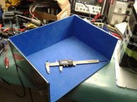
1. What are those blue sheets lining the aluminum case? Foam? Insulation? Yes it's foam for insulation and the white sheet is fiberglass for electrical insulation form the conductive aluminum in case of intense vibration and short circuit
2. Are those yellow ring connectors crimping connectors used in the automotive industry? Yes these are for 12-10 AWG wire from automotive industry
3. What are those molex connectors on the right hand side of the picture for? These are the BMS cell level connector for cell monitoring and balance These come with the Agniusm kit.
4. What sizes are the parallel cabling and output cabling? These parallel cabling are 10AWG 200 degree C silicone wires from turnigy and the output wires are 6AWG flexible wire from industrial supply