When you switch on, you connect + to - via 200k ??According to the datasheet for the Nano versions I have, the onboard regulator can handle 5-20v input. So a 12v supply could run the Nano and drive the gates.
View attachment 347026
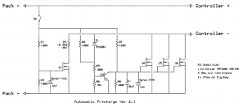
Back on the analog front, I figured out I didn't need Q2 and just the diode will take care of turning off Q3.
The R5/R6 divider controls the point at which Q3 turns off and allows the main FETs to turn on. Roughly 5v with the shown values.
View attachment 347027
You are using an out of date browser. It may not display this or other websites correctly.
You should upgrade or use an alternative browser.
You should upgrade or use an alternative browser.
Active pre-charge/inrush control
- Thread starter boo
- Start date
Not sure I understand your question. At 100v, 200k would give a current of 0.5ma, which is reasonable.
Powervelocity.com
100 kW
Good discussion. I was going to mention the same thing about the duty cycle control option. There are specialized drivers that do just that but of course no reason why an MCU can't do it. I was going to try it with my controller design. The idea is to limit the current with very low duty and monitor the voltage rise. The added benefit of doing it this way would be also checking for short and faults before attempting to turn the controller on. This an approach used in many EV designed: the contractor closes only if critical systems pass the tests.
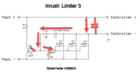
From my experience, however, the original v1, v2, v3 of the pre-charge circuit extending Miller plateau works fine though up to a certain battery voltage and if two-way switch is used. The critical part is to keep the gate to the ground and do not allow it float. The turn-off enhancement circuit (diode+transistor) helps to discharge it faster but can't be relied on for keeping the gate in the defined off state. Another thing I noticed is that if the circuit was used in always-on configuration (pre-charge on batt connection only), there is a spike every time the battery is connected. It seems to be coming from the DC link capacitors via C1 and R2, since both the main caps and C1 appear as a short until charged. This doesn't happen when the switch is in the OFF position (gate is clamped to the ground).
From my experience, however, the original v1, v2, v3 of the pre-charge circuit extending Miller plateau works fine though up to a certain battery voltage and if two-way switch is used. The critical part is to keep the gate to the ground and do not allow it float. The turn-off enhancement circuit (diode+transistor) helps to discharge it faster but can't be relied on for keeping the gate in the defined off state. Another thing I noticed is that if the circuit was used in always-on configuration (pre-charge on batt connection only), there is a spike every time the battery is connected. It seems to be coming from the DC link capacitors via C1 and R2, since both the main caps and C1 appear as a short until charged. This doesn't happen when the switch is in the OFF position (gate is clamped to the ground).

Last edited:
Thanks for explaining the pitfall of the old Ver. 3 circuit. The latest V. 6.1 should avoid this.
With a "real" gate driver that can slam the FETs on fast, small pulses should be able to stay in the safe operating area even with high currents. I know my battery spot welder can handle incredibly high currents without blowing up. Higher voltages make things harder though. The two-stage design with a precharge resistor should be pretty robust and this is how the large EVs do it.
With a "real" gate driver that can slam the FETs on fast, small pulses should be able to stay in the safe operating area even with high currents. I know my battery spot welder can handle incredibly high currents without blowing up. Higher voltages make things harder though. The two-stage design with a precharge resistor should be pretty robust and this is how the large EVs do it.
what part is suitable for Q3? Q1 can be the same as Q4,5...?According to the datasheet for the Nano versions I have, the onboard regulator can handle 5-20v input. So a 12v supply could run the Nano and drive the gates.
View attachment 347026
Back on the analog front, I figured out I didn't need Q2 and just the diode will take care of turning off Q3.
The R5/R6 divider controls the point at which Q3 turns off and allows the main FETs to turn on. Roughly 5v with the shown values.
View attachment 347027
Q3 can be just about any small signal NPN transistor with a voltage rating higher than the maximum pack voltage. For a through-hole version, something like a MPSA42 (300v) or 2N5551 (160v) should work fine.what part is suitable for Q3? Q1 can be the same as Q4,5...?
Yes, Q1 would be the same as Q4,5, etc. These should have adequate voltage rating and a low Rds. Depending on the maximum controller current, you can estimate the heat dissipation at full load and try to keep the dissipation under a few watts.
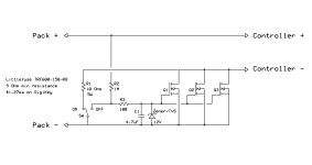
Not true. The voltage on the gates of the FETS is held low by the discharged capacitor. It will vary depending on the threshold voltage of the FETS used, but they'll start to conduct a little when that voltage gets to around 4V. Charging through a 1MOHM resistor from say 40V this will take 0.5 seconds. It'll take about the same amount of time for the gate voltage to reach 8V at which point the FETS will be conducting fully.This circuit does not work. As soon as you open the switch from the off position, the controller gets full voltage, Seems the 10Ohm is useless.
View attachment 347541
So you have about 1 second, during which, the controller is being powered or partially powered via the 10Ohm resistor.
The 100Ohm resistor limits the discharge current through the switch at turn off. Without it, the contacts would burn and the switch would fail.
Well I have build it. And it does not workNot true. The voltage on the gates of the FETS is held low by the discharged capacitor. It will vary depending on the threshold voltage of the FETS used, but they'll start to conduct a little when that voltage gets to around 4V. Charging through a 1MOHM resistor from say 40V this will take 0.5 seconds. It'll take about the same amount of time for the gate voltage to reach 8V at which point the FETS will be conducting fully.
So you have about 1 second, during which, the controller is being powered or partially powered via the 10Ohm resistor.
The 100Ohm resistor limits the discharge current through the switch at turn off. Without it, the contacts would burn and the switch would fail.
What didn't work?Well I have build it. And it does not work
What FET's did you use? There are quite a few FETs available that have logic level drive. These will start to turn on at about 2-3V VGS.Well I have build it. And it does not work
You can adjust the timing by increasing the value of the capacitor.
nicobie
100 MW
Are you positive that you have built it right?Well I have build it. And it does not work
I used this Mosfets
Infineon Technologies IRFB7730PBF MOSFET 1 N-Kanal 375 W TO-220AB
And yes I am sure I have built it correct. Did it 2 times. Same result, in the moment you open the switch from the "off" pos, the esc is switched on.
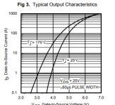
So those FETs start turning on around 4 volts, which is fine. Assuming you have, in fact, constructed the circuit correctly, I guess that the questions have to be:
1. What battery pack voltage are you using?
and
2. How much input capacitance is there on the controller?
Im unfamilliar with typical values here, but, if it was 10000uF, then a 10 ohm resisitor would charge that to 2/3rds of Vsupply in 100mS..
And perhaps 3. When you say "The controller gets full voltage straight away", what do you mean by "Straight away"? ie are we talking <100ms, or <1s
Battery voltage is 14S Liion so around 54VView attachment 347939
So those FETs start turning on around 4 volts, which is fine. Assuming you have, in fact, constructed the circuit correctly, I guess that the questions have to be:
1. What battery pack voltage are you using?
and
2. How much input capacitance is there on the controller?
Im unfamilliar with typical values here, but, if it was 10000uF, then a 10 ohm resisitor would charge that to 2/3rds of Vsupply in 100mS..
And perhaps 3. When you say "The controller gets full voltage straight away", what do you mean by "Straight away"? ie are we talking <100ms, or <1s
capacitance is 6x 560µF
I can not measure the time. And I did not use a switch, but a wire to manually "do" the switch. So my switching time might be longer than 1 sec. In this time the controller already got full voltage, before I "switched" to ON position.
Thanks for the info. So that 10ohm resistor is going to power up your drive in something like 40ms.. Which is why it feels like it turns on straight away. What it's actually doing is limiting the inrush current to 54/10=5.4A. Which is what it's supposed to do. About 1 second later, the FETS turn on and you can now draw 100's of amps from the battery pack.Battery voltage is 14S Liion so around 54V
capacitance is 6x 560µF
I can not measure the time. And I did not use a switch, but a wire to manually "do" the switch. So my switching time might be longer than 1 sec. In this time the controller already got full voltage, before I "switched" to ON position.
This is exactly how the circuit works.
Well, as mentioned the esc had full power before I could switch to the 10Ohm resistorThanks for the info. So that 10ohm resistor is going to power up your drive in something like 40ms.. Which is why it feels like it turns on straight away. What it's actually doing is limiting the inrush current to 54/10=5.4A. Which is what it's supposed to do. About 1 second later, the FETS turn on and you can now draw 100's of amps from the battery pack.
This is exactly how the circuit works.
Then I offer my apologies, but I am 100% sure you have made a mistake in your implementation of this circuit.Well, as mentioned the esc had full power before I could switch to the 10Ohm resistor
A larger value of C1 will slow things down. Moving a wire manually from one point to another is way slower than a switch.
The more complex V6.1 should avoid this issue since Q3 will keep the FETs off until precharge is complete (which won't take long).
The more complex V6.1 should avoid this issue since Q3 will keep the FETs off until precharge is complete (which won't take long).
Nice.
I'm curious if you can feel any heat on your 10 ohm resistor after turning on. A smaller wattage resistor might work.
I'm curious if you can feel any heat on your 10 ohm resistor after turning on. A smaller wattage resistor might work.
JackFlorey
100 kW
Note that it is quite possible to not notice much heat being generated and blow out the resistor anyway. Internal temperatures do not always match external temperatures, and very rapid internal temperature rises can fracture ceramic resistors even if they aren't particularly hot when they fail.I'm curious if you can feel any heat on your 10 ohm resistor after turning on. A smaller wattage resistor might work.
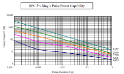
Some resistors (called pulse-withstanding resistors) are spec'd to handle such surge loads. In such cases, you have to know the pulse width of the load as well as the total power dissipated. For these resistors, you can see thousands of times their rated load as long as it is applied over a short enough time period.
An example of such a rating is shown below.
I am using this resitor;
 www.conrad.at
no heatso far, but I did not put any load to the system, just switch on/off several times.
About C1, this one does not have to be higher voltage that the input voltage, correct?
Hochlast-Widerstand 6.8 Ω axial bedrahtet 5 W TRU COMPONENTS TC-PRW05WJW68JB00203 1 St. kaufen
Großes %brandid% Sortiment ➤ Hochlast-Widerstand 6.8 Ω axial bedrahtet 5 W TRU COMPONENTS TC-PRW05WJW68JB00203 1 St. ✚ Expresslieferung ✓ Versandkostenfrei ab 69 €
About C1, this one does not have to be higher voltage that the input voltage, correct?
The heat will only happen when switching on. Once the FETs turn on, there won't be any resistor heat. I think it would only be a problem if the controller caps were huge or you were running over 72v.
C1 needs to be rated for over 12v. Typically you can find ones with 16v or 25v rating. Anything higher than 12v will work.
C1 needs to be rated for over 12v. Typically you can find ones with 16v or 25v rating. Anything higher than 12v will work.
Last edited:
Similar threads
- Replies
- 8
- Views
- 1,038
- Replies
- 9
- Views
- 1,908
- Replies
- 25
- Views
- 2,894
- Replies
- 5
- Views
- 3,303


