Active pre-charge/inrush control

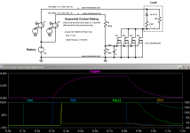
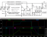
In some applications it is desirable to have no switch, just connect and disconnect power without inrush or arcing. This can be done using sequential contact mating as I show in this spice simulation. The output mosfets are off at the right times because M2 turns off the gate voltage during contact sequencing V(stop). M1 turns M2 off to start precharge and run the load while fully connected. Load current I(S1) is zero during connect and disconnect. The contact sequence is shown with 0.1 second spacing but can be much faster. A connector such as the Anderson PowerMod with pre-mate(a), standard(b), and post-mate(c) pin lengths can provide the sequencing. I don't plan to build this version because I need a switch so it is untested.
precharge sequential.PNG
 
KeithT said:
In some applications it is desirable to have no switch, just connect and disconnect power without inrush or arcing. This can be done using sequential contact mating as I show in this spice simulation. The output mosfets are off at the right times because M2 turns off the gate voltage during contact sequencing V(stop). M1 turns M2 off to start precharge and run the load while fully connected. Load current I(S1) is zero during connect and disconnect. The contact sequence is shown with 0.1 second spacing but can be much faster. A connector such as the Anderson PowerMod with pre-mate(a), standard(b), and post-mate(c) pin lengths can provide the sequencing. I don't plan to build this version because I need a switch so it is untested.

First. As I am fond of saying, I know just enough about electronics to be dangerous. Ie. I know enough to have questions, but not enough to work out the answers for myself; or even know they are stupid.

So, bearing that in mind, that seems like an awful lot of components for arc suppression.

If you have a pre-contact connected to the main contact via a (say) 10k resistor, the when the first contact is made, no arc occurs because the resistor limits the current, but the male contact gets pulled up to the same voltage as the female. And once the second contact is made, they are at the same potential, so no current above the load demand can flow, so no arc? Once both contacts are made, both ends of the resistor are at the same potential, so no current flows.

I've seen that an RC circuit is often used for this, and *think* the purpose of the C is to slow down the current build across the load; and this is the "inrush suppression" part of the deal.

I'm hoping you might answer a couple of questions for my education:

1) Is my laymans description above roughly correct?

2) If so, what more does your (to me) complex circuit do for me?

Feel free to ignore is this is just too dumbed down.

Cheers, Buk.
 
An RC circuit can be used for the precharge but it will be very slow depending on the values. My simulation shows a 1m (1,000uf) load capacitor. That 10k will take more than 30 seconds to reach 95 of the 100 volts I have. Charging at a constant current through the mosfets gets to full voltage in 0.2 seconds. And the precharge is to avoid inrush current on connection not for arcing. It will arc on disconnect if there is load current. Using the mosfets to switch off the load current means there will be no arc on disconnect. That can only be prevented by turning off the load by some means, generally a switch. So yes, this may look complicated, but I think it is the only way to do this without a switch.
 
KeithT said:
An RC circuit can be used for the precharge but it will be very slow depending on the values. My simulation shows a 1m (1,000uf) load capacitor. That 10k will take more than 30 seconds to reach 95 of the 100 volts I have. Charging at a constant current through the mosfets gets to full voltage in 0.2 seconds. And the precharge is to avoid inrush current on connection not for arcing. It will arc on disconnect if there is load current. Using the mosfets to switch off the load current means there will be no arc on disconnect. That can only be prevented by turning off the load by some means, generally a switch. So yes, this may look complicated, but I think it is the only way to do this without a switch.

That makes sense, even to me. Thank you.
 
I'm actually using a 4.7k 5W resistor and a light switch to precharge my inverter right now, while I wait for UPS to deliver parts for a better circuit (weather delays). Using a switch has a lot of drawbacks. To properly turn on my inverter with a load I now have to do this:
1. Make sure the load is turned off
2. Make sure the inverter is turned off
3. Make sure the light switch across the precharge resistor is turned off
4. Close the contactor
5. Wait one minute for the inverter to charge
6. Turn the precharge light switch on
7. Turn the inverter on
8. Turn on the load
Turning off is almost as bad.
1. Turn off the load
2. Turn off the inverter
3. Turn off the precharge light switch so it's ready for next time
4. Open the contactor
Forgetting, skipping or rushing any of these steps can damage a switch or contactor. And you might not even know it happened until it fails later. So a circuit that lets you just connect and disconnect to live power with the load on with no worries, that's pretty nice I think.
 
Food for thought; another possible approach to this problem is to switch the main FETs on hard instead of slowly ramping things up. You'd still need a time delay in the case of not using a switch. Based on what I've seen with the spot welder circuits, I think the FETs would be OK with a fast turn-on. This might make things simpler and reduce the parts count.
 
Here's a very simple version. It works, there is no inrush current through the make-first contact. However there is a difficult trade off in the value of C1. Making it larger reduces the current surge through the fets but also delays the turn off. That means there must be enough time between break-first and break-last to turn off the fets as the gate voltage decays or there will be arcing on disconnect. The 1uF value shown is probably enough to keep the fets in the Safe Operating Area but it is close. There is a current pulse more than ten times the value of the other circuit and it occurs while there is high voltage across the fets. Making C1 larger will reduce the current by slowing down the turn on, but it will also slow down the turn off. In an application where there is a slow movement operating the contacts, like a large lever, that would be ok, but it starts to resemble a switch!
precharge-simple.PNG
“Make things as simple as possible, but no simpler.” Albert Einstein
 
That looks a lot like one of our earliest versions. Lots of blown FETs unless you make it super slow.
 
Yes, I learned about SOA working on high power audio amps in the early 70's. Breakdown voltage and current ratings don't cover the situation when both voltage and current are high. In audio that happens with reactive loads. It causes localized heating on the chip that then results in catastrophic failure. The fets I'm using are rated to handle around 6 amps and 60 volts for 10 milliseconds. More time, voltage or current together and bang. I see that it is not quite the same thing with mosfets as bipolar but it is similar in practice. https://en.wikipedia.org/wiki/Safe_operating_area
 
If you look at the SOA graph for your FETs, you'll probably find this application put them outside of the envelope, but since it's a single event, they seem to survive. The die can absorb some of the heat.

The early precharge circuits just used a RC on the gate to slow the turn on, with no feedback from the load. A lot of guys blew up FETs trying this. It would work if you got the speed right, but it's only when passing through the gate threshold voltage where it needs to be slow.

I have a circuit I breadboarded but never tested with a real load that uses a gate driver chip. The chip has UVLO so it won't come on until it has enough voltage to fully turn on the gate, then it just slams them on fast. I think it will work and solve a lot of issues, but the chip only comes in SMD and is pretty tiny.
 
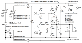
Here's a circuit that will turn on the fets very fast using a discrete schmitt trigger. I have no idea if the fets would survive. Spice shows a peak dissipation of 2295 watts but it's over in 3 microseconds. So the energy is only 0.0037 joules, maybe that's ok, or not. Certainly is a different approach to the problem. Who wants to try it?
precharge-schmitt.png
 
I think it will work, but it needs to be tested. My spot welder uses the FETs to switch against essentially a dead short, with current over 2000A and they work fine.
 
I'll probably try it. Those fets are rated 240 amps for 100 uS, this is much less than that. SOA has 100A at 100V for 100uS so good there too. I haven't figured out how to turn it off yet.
 
For turn off, you could borrow part of the circuit below (done by one of our members long ago). Just substitute your Schmitt trigger for the input. This circuit provides a fast turn off even with a slow input.

The gate driver chip I found can reduce the parts count quite a bit, but maybe not the cost. I don't have my notes on that here, but next week I can post it.


Randomly Opto Cutoff.jpg


Edit: I did find some notes. The chip I was looking at is a IRS44273. $0.84ea.
Datasheet: https://www.mouser.com/ds/2/196/irs44273l-1228507.pdf

The UVLO feature would allow you to slowly bring up the voltage on the chip and it would only turn on when it gets over the lockout voltage. A RC could be used on the input to give a time delay. The chip needs a voltage regulator for it's supply, which would also be the gate drive voltage.
 
Turn off is straight forward with low side contact sequencing or break first switch before disconnect or switching off. Load turn off is fast without any need for positive feedback. This turns on and off a 1,000W 1mF load with very low switching dissipation, about 1mJ per fet. There is a very brief current spike to charge the gates at connect but I don't think the contacts will mind. It will ring with wire inductance against the load capacitor and can't really be simulated so I'll see how it does in the real world soon.
precharge-schmitt-sw.png
precharge-schmitt-bd.png
That's a nice simple driver chip but regulating down from 116v would take some doing.
 
The real world has spoken and, well, I've joined the blown fets club. It did work at first. I brought it up slowly and carefully, first test with a load was driving a 100W incandescent light bulb. That is 10 ohms cold so it has a real inrush. That worked exactly as expected. I changed the circuit slightly from the last post, added a diode in the emitter of Q1 and increased C1 to 47uF. That gives a nice turn on delay of about half a second and keeps the capacitor voltage polarized. So the light bulb came on with a noticeable delay and all was well. I have the PowerMod connector with pre-mate pins for power and ground and post-mate for the pre-break disconnect turn off. Plugging and unplugging with the light bulb was flawless, no pop, no arc, very nice.

OK, the reason for building this was to drive my inverter so that was next. I hot plugged it with the inverter connected and got a very nasty pop, oops, that wasn't in the plan. Went back to the light bulb load and no delay, looks like the fets are shorted. Ohmmeter verifed that and the autopsy showed two of the four are dead shorted, the other two apparently ok, but I won't use them again.

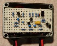
So I'll show the construction. It came out nice and I'll do something similar for plan B, not sure what yet. I used a very small aluminum enclosure so it was a little bit of a challenge to fit it in. Fets are mounted insulated and wired like this
mosfets.jpg

A couple of screws hold the vector board with the schmitt driver above the fets

schmitt.jpg

Here's the bottom to show the wiring. Four connections to the board, plus, minus, gate and pre-break.
bottom.jpg

Here's the whole thing with it's light switch and resistor predecessor for comparison
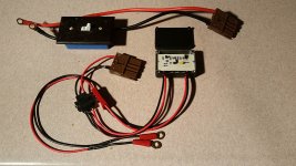
complete.jpg

So now what? I could go back to the ramp with switch version or maybe try the sequential contact switchless idea. Or I could give the gate slamming idea another go. I really like the efficiency of fast switching and the ability to connect directly to a load is nice. My simulation showed that the power dissipation during turn on with a 1kW load is 10,000 times less with the schmitt drive than the linear ramp. So why did it fail? My guess is that the transient at connection caused the gates to get turned on enough to get into the linear region, that got arcing started and bang, dead fets. So maybe another set of contacts to keep those gates really off during connection would save them. I'll decide what to do while I wait for the next UPS parts delivery...
 
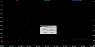
OK here's plan B. No stock on the fets I was using so I found this one, more money but pretty impressive specs. https://www.mouser.com/ds/2/205/DS100844B(IXFX-FK300N20X3)-1223807.pdf So one fet will have the same on resistance as four, easier to wire. And it should be better able to handle the inrush current, lots of SOA. I don't know the ESR of my inverter capacitor but it could be as low as 0.1 ohms. If so then the turn on looks like this, those are pretty big numbers.hot switch.PNG

Lots of circuit changes made for reliability. Make-first contacts hold the output off by turning on M1 in advance. Q3 is added to make sure C1 doesn't start to charge until all contacts are mated, regardless of timing. Connection transients are suppressed by RC networks and low current in the sequenced contacts. I added a diode on the load in case any load inductance is looking for trouble.
hot schmitt.png
Will it work? We'll see...
hot schmitt 2.png
Edit: one more RC to take the edge off the main rail connection.
 
Apologies if this has been asked before, but regarding Richard's V3 precharge circuit, could one remove R2 and C1 and use the mosfet's internal capacitance to increase the turn on delay?

The internal capacitance of this mosfet is 8000pF. Coupled with a 250M resistor R1 we get a 2s time constant. Since we still have the 12v zener, we're only concerned with the time it takes for the gate voltage to go from 0 to 12v.

With the RC circuit equation,
7feca4cabd371fb3a58e1b258e75372e.png
we get a turn on time of about 0.5s to reach 12v at the gate, assuming a 50V battery.

Anything I'm missing?

file.php
 
I think it would be like the early circuits that just used a RC to make the gate voltage rise slowly. If you make it slow enough so the FETs don't blow, it takes too long to get fully turned on. 250M resistors are not very practical either, as contamination on the PCB or humidity might be in that range.
 
fechter said:
I think it would be like the early circuits that just used a RC to make the gate voltage rise slowly. If you make it slow enough so the FETs don't blow, it takes too long to get fully turned on. 250M resistors are not very practical either, as contamination on the PCB or humidity might be in that range.

I fired up simulink this morning and tested both your circuit as well as a modified version that ditches the external cap in favor of the mosfet's internal capacitance.

On the modified version, with a 100M resistor, we see a peak current of about 600mA and nearly linear dv/dt. (Due to the zener we only see a small slice of the RC exp. decay)

I think the negative feedback in your design is quite elegant and I will probably go that route. Still, it's interesting to try another approach.
The V3 circuit simulations seem to match the behavior that you described a few pages back.

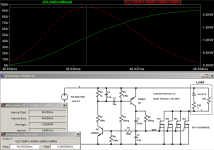
V3 circuit simulation graphs

Modified circuit simulation graphs
 
OK, I finally finished my plan B gate slam schmitt trigger design today. I had high hopes. I used a scope to verify the turn on waveform starting with a leftover fet from the first version. It worked as expected with about a 3uS switching time, independent of load. I used a 500W incandescent and a 1500W heater in parallel to draw about 17 amps at 115volts with a significant inrush. The sequential contacts worked fine, no sparks or arcs on connect or disconnect. But the scope occasionally showed a parasitic oscillation, a burst of 15MHz during the first part of turn on. I tried several circuit modifications but nothing helped.

So I replaced the small fet with the new big one that has a very high soa and low on resistance. It worked too, but the waveform was poor, huge ringing at a lower frequency including negative swings. I added a freewheeling diode and it was even worse. Then I added a 100 ohm gate resistor and it looked really nice, fast clean switching regardless of the load current.

So I put it all together with proper wire connections to the fet, short leads etc. And buttoned up the enclosure. Retested with the heater load, all good. So I connected it to the inverter with its 2500uF capacitor input. I tried it and it worked, no arc, came up to full voltage nicely after the expected half second delay. OK, I disconnected and saw that it was still charged so I connected a bleed resistor to get it ready for a second try. And BANG, big arc on connect, my fancy new fet is shorted.

So, while I still think this approach could work, I'm giving up on it, at least for capacitive loads. It did work really well with resistive loads, plug and unplug with no arcing at all, very nice. But apparently the huge current surge connecting battery to capacitor is just too much for even a state of the art mosfet. All the numbers said it should work, spice, the datasheet, scope, but the real world has spoken. This time I'm going to listen. I did learn a lot...
 
Bummer. That should earn you the Fried Guinea Pig award. An award I used to bestow to people who tried something untested and had the result of smoke release. Interesting about the ringing. I guess that's why they always use some kind of gate resistor.

What was the FET and how many did you have in parallel?
 
Here's all the details in case someone wants to pick up the pieces. I'll try hard not to do that, but I'm attracted to unsolved problems. The FET was this https://www.mouser.com/ds/2/205/DS100844B(IXFX-FK300N20X3)-1223807.pdf It is huge, only used one since it should have been enough and it cost $22! It never even got warm in my testing, no smoke either. Why did it die?
fried fet.jpg
Here's the driver board. I added lots of parts to make it better, and it was until it wasn't.
fried bd.jpg
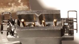
And this is the connector with sequential contacts. I think that really worked and is an essential part of hot plugging.
fried pins.jpg
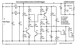
And the final schematic was this
fried.jpg
I found this app note pretty interesting, lots of good advice and warnings about device failures, even cautions against using zeners! https://www.infineon.com/dgdl/an-937.pdf?fileId=5546d462533600a40153559ea1481181 The main thrust is that the gate drive circuit needs to be low impedance. I thought a 0.1uF was pretty low, maybe not. That gate drive buffer he uses might be good.

Anyway I still need a good pre-charge gadget so this story has not ended yet. I fried my light switch too, one good turn off arc shorted it. The fet worked really well for a clean disconnect. So I have to figure out my next move. Switch? Ramp? What fet(s)? Oh here's the LTSpice circuit just to complete the package. View attachment precharge schmitt fried.asc.txt
 
Interesting what they say about using zener diodes. I think they were talking mainly about their behavior at high speed. For the case of just limiting a slowly rising voltage, I don't think there would be any issue. The ringing part is hard to model or predict.

I would guess the gate drive impedance in your circuit was too high and the FET suffered from overdissipation. The little gate driver chip I was playing with seems to have a nice, low impedance. That with the right size gate resistor should work.

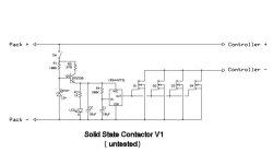
Below is a first pass schematic of the circuit I was working on, but is lacking a few things, like a gate resistor. Q5 and the zener make a simple linear voltage regulator for the driver chip. R4-C1 make a RC time delay on the input that gives time for the 12v supply to come up. The chip has built-in UVLO, so won't turn on unless there is at least 8v or so. When the switch gets turned off, the 12v supply will drop and the UVLO will kick in to turn off the FETs before the supply cap C2 drains. The LED is optional, but helps pull down the voltage on turn-off. Keep in mind this was designed for a typical motor controller that has no load other than the caps when turned on.

Using a bunch of cheap FETs in parallel seems to be more cost effective than a single expensive one, but take up more space.

SS Contactor V1 Schematic.jpg
 
I built a variation of the V3 inrush limiter design to use with my 12s 20Ah ebike pack. I'm using a normally open keyswitch to control it.
20180204_224809.jpg

I used 4 AOT290 fets in parallel, soldered to a copper plate for some heatsinking. I'm hoping this can handle 50-60A continuous. So far it is working well on my bike. It powers my VESC controller and the DC/DC module that provides 12V for lights/horn.
 
Back
Top