Adapt longboard wireless remote control to ebike controller throttle

marce002

10 W
Joined
Mar 28, 2016
Messages
77
Location
Buenos Aires
Hi

I need to adapt longboard wireless remote control to ebike controller throttle, because the logboard controller is fried and i want to place an ebike controller insted. do you think is going to be posible? how would you face this problem?
Currently the motor works fine with the ebike controller and a wired throtle.. only one motor is needed to work.
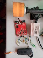
this are the elements:

20240316_141618.jpg
 
Was the receiver for the remote control embedded into the old controller? If so, you may need to buy a new remote with a paired receiver if they make one that is compatible with your new controller.
 
yes is embedded inside... jut i want to make some kind of arduino / transmision / decoding maybe interface to achieve with out buying anything... it is a hobby for me.
 
That is probably doable, but I doubt you will get away without buying anything. At a minimum you will need an RF receiver that operates at the same frequency as your remote to connect to the arduino. And, of course, you would have to buy the arduino board. Somehow I doubt it would be cheaper than buying a purpose built kit and it will certainly need more real estate to install it.

https://www.amazon.com/vanpro-Elect...11-spons&sp_csd=d2lkZ2V0TmFtZT1zcF9tdGY&psc=1

Simple PAS to throttle converter using an Arduino Nano
 
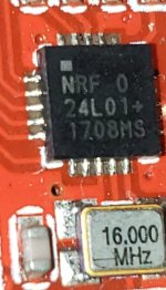
yes the receiver is currently on the board , and i could use it, is nrf24l01 and also have if necesary an arduino or atiny85 ... but the almost working red board that you see in my first picture has a section with the nrf24l0, flash mem and its 16mhz crystal, i think that part of the circuit would work fine, so wanted to use it, but need some help setting up the environment to test.. need ideas of how to test...
 

Attachments

  • CM240317-104046001.jpg
    CM240317-104046001.jpg
    691.4 KB · Views: 3
Is the red board your old controller and you want to use the receiver circuit embedded into your old controller? The nrf24l01 is a 2.4GHz transceiver on a chip. You could probably remove the components from that board and build a new circuit with them if the components are still good. You can buy nrf24l01 modules for the arduino for about $2 each. I understand it is your hobby, but why do things the hard way?

Amazon.com

I don't have any experience with building an RC receiver with an arduino, but it has been done before.
How to remotely control your Arduino with a 2.4ghz controller with less then 12$

If you are setting up a lab on the cheap, the RF Explorer is a budget friendly spectrum analyzer.
 
If the receiver portion of the original controller is still working, then after you verify all the signals and power supply voltages between it and the rest of the controller, noting them all down, you can disconnect just that part of the board from the rest of it (if you don't care about destroying the original controller), then power it from whatever's needed so it will operate. Once it's operating, then knowing what kind of signal it outputs for each remote signal, you can use an MCU (arduino, etc) to translate that to whatever your new controller accepts.

Or do as RunForTheHills suggests and use a new module with that chip on it. (but you still should test what the original outputs for varous remote signals being received).

If there's a spec sheet for the chip (or the adapter boards with it installed) then that will tell you what pins do what, and what kinds of signals it can output.

To test the one you have, you need to trace which pins on the chip are actually connected to anything outside the area dedicated to the reciever. Then measure voltages on all those connections, with the controller just sitting there powered on, and with the remote being used in all of it's possible ways. If you have an oscilloscope you can also verify if the control outputs of the chip are using a digital signal to teh controller's MCU to operate the motor; otherwise you'll have to just note down what voltages you see at various throttle positions, and if you have a frequency counter in the multimeter, use that to see if it detects anything (if it doesn't, it's just analog voltage like a normal throttle, if it does, it's a digital signal of some type, and knowing what that is can help decode it).


If not, and if you know what signal is output by the remote, on what frequency, you can design and build a receiver for it, and then have that receiver translate the signal instead.

Or you could gut the throttle remote, take a pair of something like the ESP32 in one of it's many versions, which have BT, wifi, etc all built in, and use one to read your trigger/buttons/etc on the throttle remote, and have the other one receive that signal and translate it to whatever your new controller accepts.
 
Last edited:
Or do as RunForTheHills suggests and use a new module with that chip on it. (but you still should test what the original outputs for varous remote signals being received).
He doesn't really need the outputs of the old transceiver circuit if all he wants to do is control the throttle on the new ebike controller he has installed with the arduino. He needs to simulate an ebike throttle to the controller and needs to decode the RF signal for the throttle control from the existing remote that he wants to reuse.
 
Back
Top