Add this thumb throttle to sensorless hall controller

marce002

100 W
Joined
Mar 28, 2016
Messages
186
Location
Buenos Aires
Hello

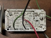
i have this controller with a non hall motor... now works with a single push button ( to full power)... bought like this... want to add this thumb throttle and I need help to wire to controller board....please look in the pics..thanks in advance...

for reference throttle wires
green = battery power max 50v? tested
yellow brown= switch
blk white red = normal throttle connection .8v to 4.1v

do not have idea what this labels in the board means:

HX HV VL ZF VP
only VL is used and 5v is there ....

I do not know how the button is connected is sealed.


DO NOT READ THIS IS IRRELEVANT( for the issue)
for reference only tested:

at 50v 3 leds will be on : FULL HALF EMPTY
when 36v appears in battery power then FULL turns off only 2 remaining..
when 32v or less only red EMPTY ARE ON
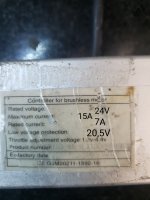
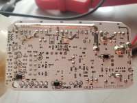
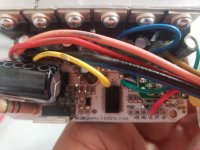
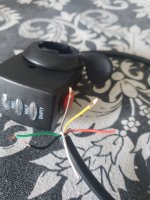
20241229_174452.jpg20241229_155118.jpg20241229_155129.jpg20241229_174532.jpg
 
Last edited:
yes is easy to note 3 phase wires going to motor ( yell gree blue) ..... then i have "pink light" and "pink dark" .. the first in GND and the dark is VL always 5v present...
the switch joins gnd with VL in the board... mmmm not clear to me how this works...thks ehp

note: it would be great if someone could give an idea of what this pins are in board:

20241229_194944.jpg

and also how do you turn on this controller? if i need to power on with that swich yellow and brown do this controller have power line on off or power lock somewhere in board? so where to connect the switch yellow and brown wires....
 

Attachments

  • 20241229_192845.jpg
    20241229_192845.jpg
    1.7 MB · Views: 6
  • 20241229_192853.jpg
    20241229_192853.jpg
    1.2 MB · Views: 6
Last edited:
ok at least someone tell me where to connect yellow and brown switch so the battery does not get depleted .... ignition lock ia a feature I imagine this controller has
... i can live with no throttle but need ignition lock pins...thka
 
I just ended up with one of these same controllers and I got it to work with a hall throttle.

Throttle wiring is:
5v ref wire (red) to 5v port on the board
Ground (black) to any ground location
Signal wire to HV (green for me probably white for you)

Also figured out that BK1 and or BK2 connected to ground will interrupt the throttle.
IMG_2688.jpeg

Can you share the location you are using as a power switch?
 
I just ended up with one of these same controllers and I got it to work with a hall throttle.

Throttle wiring is:
5v ref wire (red) to 5v port on the board
Ground (black) to any ground location
Signal wire to HV (green for me probably white for you)

Also figured out that BK1 and or BK2 connected to ground will interrupt the throttle.
View attachment 368327

Can you share the location you are using as a power switch?
If you asking about a switch to switch the controller on and off, your controller isn't designed for one, though you can still fit one.

The red battery wire is soldered to VDD. It branches one way to the MOSFETs to power the motor and the other way to power the controller. Normally, it goes direct to the big resistor (RT1), then to the 12v regulator (U8), then the 5v regulator (U1?), but yours might have something else before the resistor. Ideally, you need to cut the track on that side of VDD as close as you can to VDD, then you can put a switch across that cut. That's how all ignition switches and LCD/LED control panels work.
 
Thanks. I see a location Marked SW that is currently shorted to I02 which looks to come straight from VDD. I'm thinking that is a perfect location for a switch. I'll desolder and find out.

Nothing like wasting hours on a virtually worthless controller to placate my curiosity while my real projects sit idle. :)

UPDATE- That SW to I02 was indeed the correct place for an on/off switch.
 
Last edited:
Back
Top