• Hello ES! We could use some help to get us past the finish line on building the new knowledgebase for the forum.
    Can you donate? Please see our fundraising page. Thank you!

Adding 5 Pin display to controller

Technologia

New-ish here
Joined
Sep 4, 2025
Messages
42
Location
India
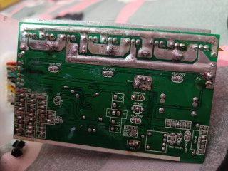
I have these two controller,both pcb looks similar,both are 48v 500w,but one has 5 pin s866 display support but another has only single pin display/speedometer output wire. While both pcb match, i figure out all the pins for 5pin display,so if i connect them will s866 display work on another controller ??
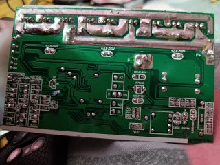
 

Attachments

  • IMG20251031134301.jpg
    IMG20251031134301.jpg
    3.3 MB · Views: 21
  • IMG20251031134115.jpg
    IMG20251031134115.jpg
    3.2 MB · Views: 19
Have you used either controller and know that they work when wired up? Never seen a controller with a single wire output for a speedometer. Why don't you tell us how the connections will differ between the two setups, using the names of the pins.

I don't think your idea will work. The right hand side of the board has a port used for JTAG programming, probably used to load the firmware into the board's microcontroller. They probably use this to set the board up to recognize its S866 inputs, Then again, I'm just a crusty skeptic I don't feel it's worth the time to experiment., unless you want to learn..

Good luck.
.
 
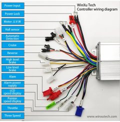
Look at this image, speedometer single wire(purple)
 

Attachments

  • IMG_20251031_202204.jpg
    IMG_20251031_202204.jpg
    496.3 KB · Views: 13
Look at this image, speedometer single wire(purple)
The single wire is usually used as a speed pulse input to a speedometer, or display like the CT-22, that only provides display status functions (receives signals, but doesn’t communicate back to the controller).

Looks like you may have a link to the controller(s). Can you post it?
 
Last edited:
Back
Top