liveforphysics
100 TW
gwhy! said:hall sensors arrived, and I have made a start
On schedule to have them all finished by the end of this week.
Wow! Those look fantastic! Nice job!
gwhy! said:hall sensors arrived, and I have made a start
On schedule to have them all finished by the end of this week.
Thud said:Gwhy,
you say larger ones....does that mean 80mm motors? or another version of your 63mm units? I am eching boards to hold the halls & wires in my v2 molds myself....your way ahead of me though.
 , 63mm and 80mm but spaced at 60d
Phew! My 63mm just arrived today and I thought I was gunna have to make my own hall array...gwhy! said:Hi Thud,
The larger spaced ones , 63mm and 80mm but spaced at 60d
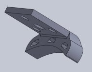
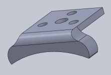
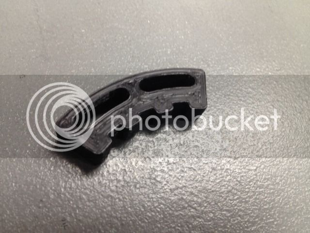
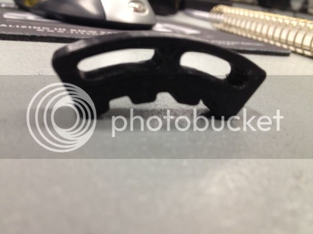
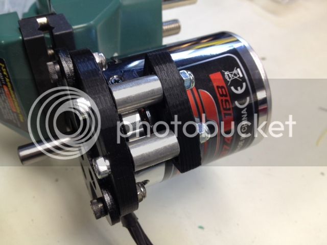
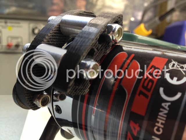
tuurb said:I am also trying to make my own brackets, wich I will 3d print,
I found on endless sphere that a lot of people use the S411A from Honeywell with 17,14° spacing so I tought to do thesame.
Below my temporally design of a bracket for use on my HK 6364 213rpm/V BLDC motor, I will be using the 150Amp HK car ESC.
I think of installing the mount at a distance of 3mm from the spinning motor:
like this the centerpoint of the sensors will be at around 4,5mm from the outside can of the motor...
Any remarks or ideas?
Maybe another sensor is better for this application?
Or other spacing?
Or another distance between sensor and motor?
(I have zero experience with adding hall sensors, BLDC motors or ESC, but I'll learn!)
Thanks in advance!
Tuurb
spkpn said:Hello,
I might be interested in halls that can be mounted to the turnigy 80-100 series motor. But only if a mechanically untalented guy like me can acomplish the job
rgrds,
spkpn
2moto said:I haven't read the entire thread (too long!!) so this may be blasphemy. Going back a few years, at a brushless motor company we experimented with various types of commutation sensors on brushless motors. By some margin, optical sensors produced far better accuracy which a good controller can use to its benefit for switching phases. Hall effects, although convenient and cheap, have various drawbacks, some of which have already been highlighted in this thread (from the bits I did read).
For this motor, I would design an optical interrupter type arrangement which will work well. Of course, there are dust and environmental issues to solve. But still, for the performance advantage, I would chose this direction. With good shielding, you should be able to get something to work where marks on the spinning "bell" are being picked up by reflective optical sensors located around the periphery.
No, no, no, must resist, must resist! Too many projects!
Miles said:See: http://www.endless-sphere.com/forums/viewtopic.php?f=2&t=28966


Doesn't matter as long as they are separated by 120 electrical degrees.HumboldtRc said:Should I be installing the hall sensors with the writing facing in or out?
crazyscow said:I had a question, i sadly have a outrunner with 24 stator and not enough space to fit the hall sensor horizontally, would it work if i use vertical?
incase i would want to fit them outside, how far would it have to be away from the engine?
cheers
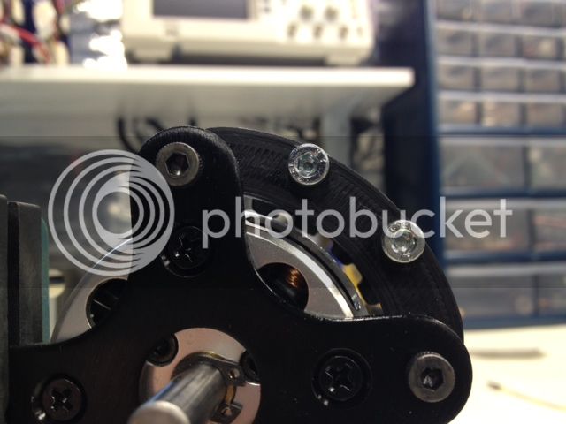
).From factory it is common to have all lams conduct if you mesure from one end to the other with a multimeter the coating they have on them usaly does not realy stop them from conducting. You can try to spin it up to max rpm and see if the part you machined is getting very hot.NickB said:I'm trying to fit internal hall sensors to a turnigy rotomax 100cc.
The slots in between where to small to fit the hall sensors so I used the dremel to mill them out a bit.
But then I realised that by milling the stator I will short out the lamelles (don't know if this is the word
By measuring with a multimeter the first 10 lamelles or so are shorted.
Does this make the motor unusable?
I noticed the sensors do fit under the slots next to the windings (picture), is this also a possibility?