Air-cooling the moving hub motor

Joined
Apr 25, 2014
Messages
2,801
Location
Sausalito
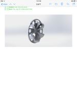
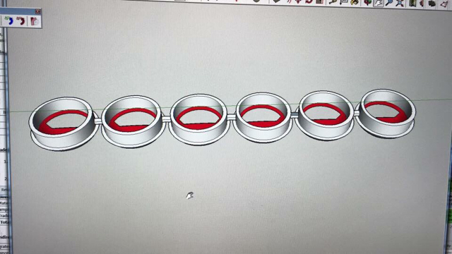
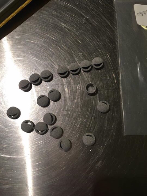
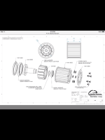
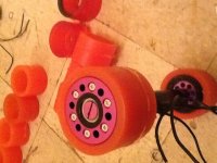
I want to get the best air cooling possible from a small part I'm going to get made(3D print or later pour in plastic) that I'll glue on the outside flange of my skateboard hub motor. It is always rotating with 6 holes and the motors get hot and the holes are very under utilized.

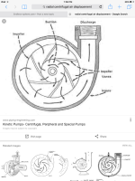
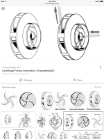
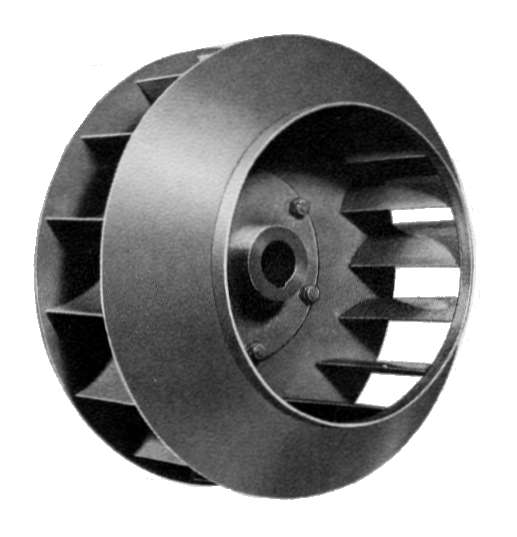
I liked the air scoop design below and was going to get that printed but then now for differnet reasons the other design using centrifugal force to throw the air out instead of scooping it I. seems a better idea. The scoops can only work at the 3 to 9 o'clock upward position but the other design the blades could be shaped to eliminate the pressure in those upward positions. Does this throwing of air instead of scooping method of cooling work best on a moving wheel?

There are other holes on the backside of the motor as well
 

Attachments

  • image.png
    image.png
    87.9 KB · Views: 3,086
  • image.png
    image.png
    206.7 KB · Views: 3,086
I recently 3D printed some Alumide vents to create a Venturi effect on Ebike hubs. You're welcome to the model.
54cb67bd4f1996e10c3701a138dfb47d.jpg
54ffeac0b98adf00fd93eb840102b5fb.jpg


Sent from my iPhone using Tapatalk
 
How effective are they? I still don't understand how these would work but I understand the Venturi effect. Have u tried other airflow designs?

It seems centrifugal force and attempts to scoop air in are at odds with each other

At this point I'd like to try to make something that will work on the centrifugal force as in the pump shown which emits air instead of pulling it in.


I also like this:
https://en.m.wikipedia.org/wiki/Tesla_turbine


Im interested in the material you used as well for doing printing and wonder how well it can sustain high heat and not soften :https://www.shapeways.com/rrstatic/material_docs/mds-alumide.pdf
Says it's melting temp but surely it softens before then. I'd like to print out the complete flange above which would serve to hold on the tire and also move air through the 6 holes on both sides
 

Attachments

  • image.png
    image.png
    100.9 KB · Views: 3,043
  • image.jpeg
    image.jpeg
    119.9 KB · Views: 1,799
the heat pick up would improve with circulating air through the motor, so one side could be shaped to push air in and the other side pulling air out,
u could imagine your outrunner as a radial radial pump impeller by itsef
that's how a hacker motor outrunner seems engineered such as the one of my e board : 100% radial inlet on the stator driving end -> "facing in" axial empeller on the rotor side of the driving end -> 100% radial outlet impeller on the rotor non driving end
there is actually no axial holes on this motor, they can hardly "catch" air

have you considered statorade, Hummina ?
 
I'll have to check the hacker motor design. My motors have lots of holes and I think the statoraide would get out. As it is now the holes don't do anything. Coming up with a design that does the MOST air transfer is my goal but I don't even understand what forces are at play. Ideally I'd like to 3D print a flange, instead of using the thin purple aluminum I use now, and the design options are practically limitless. Even if the material can't take the heat I could glue the 3D print on the flange. I could use any design, have it come way out the side of the motor, but I don't know what to make. As it is now I'll be testing the scoops above but feel there's likely a much more effective design
 
The hacker site doesn't explain much as far as I could tell but the corkscrew motor they have...I couldn't even find out if it was an inrunner.

I'm surprised there isn't more research and results out there revealing what air-cooling design would be optimum for a bike wheel at least. A good means of cooling could greatly increase the motor's possible output before it gets too hot. Keeping things cool also greatly helps with efficiency as copper resistance from 20 degrees Celsius to 120 Celsius goes up 40 percent

I've gotten the air scoop design printed and will compare it against a centrifugal design I'm getting made that uses backward sweeping curved blades (Quieter I'm thinking if I have the blades curved to enough (1/4 circle) they maybe wouldn't experience any of the oncoming air pressure pushing back in ).

This pic is pretty much what I'll get made. It will also have an inner layer which will bring the 6 motor holes to the central resevoir that feeds the blades

I'd like to find a 3D print material that can take 250f continuously so I could solely use the 3D print as e wheel-holding flange instead of having to glue the print to the aluminum flange I'm using now
 

Attachments

  • image.png
    image.png
    173.6 KB · Views: 2,992
Friend go get PETG! You won't melt it or make it softer before you close in 200 degrees Celsius.

This kind of design is a good idea, I'd love to try some air flow too on my hubs. But Given the few millimeters of space I can use, it will be hard!
 
I've plenty of petg. It lacks thermal transmissibility of Alumide.


Sent from my iPhone using Tapatalk
 
Samd how do ur plugs work? Do they work? They seem so small. Tomorrow when I get ahold of the 3dman I'm tempted to do a huge one. A middle and a small. It's not to expensive considering how awesome the potential is. Have to try it.
I'll see if I can get some of the high heat petg. I imagine it'd not run of the mill stuff. If u know a place that uses it and is cheaper and good please tell.
 
Which temperatures do you need? If you need 250 degree F that's equivalent to 120 degrees C, you're covered with classic PETG like eSun up to 200 degrees C.

Cheap and easily available and good quality (no dust or anything in filament).

Now as Samd pointed out if you also need the fan itself to absorb heat so it can take a bit of heat and cool by itself with cooling, that's not the best option but apart from Filaflex maybe, which is a soft material with easy thermal absorption (and if I remember lower melt point) I don't see printable filaments adapted.
 
What kind of rpm will your motor run? I run more power through a hubmotor than anyone on the forum at conservative settings of 28kw peak, yet my motor runs cooler than most. I know how to cool a hubmotor. eg I can take off from the house for an 8 mile run at speeds up to 60-70mph for the highway portion of the ride with a small mountain climb included, and I've seen stator temps as low as 68 celsius at the end of that run to the hardware store. If I show off a lot on the highway embarrassing car drivers by using heavier throttle, the increased current levels result in higher temps, but I never reach the danger zone. The highest temps I've seen were 103.

I use intake holes on one side and perimeter exhaust holes and centrifugal blades on the other side. This type of cooling works best at higher rpm, so the 20mph with 26" wheel crowd need not apply, along with those putter around off road at relatively low speeds. I take it you have a small diameter wheel, so your rpms should be relatively high.

FWIW those little plastic button things aren't going to move much air at any rpm. Look at fans for blade designs, though axial fan blades with their beautiful curves that are mostly for marketing purposes aren't appropriate. You're doing a radial fan. As far as "scoops", a big static scoop to help air into the intake side is the way to go, because it would slow the flow past and increase pressure for better intake flow. I've never had to go to that extent though I have ideas guaranteed to work.
 
What's to stop us from cooling the crunk out of the motor with whatever the tech is these days? Other than the complication of the device ..if I can cool a small motor can I get it to do a big motor's job? will iron losses rise while I keep the copper loses Steady? Heat in my motor is the limitation and I can blast out of the house and not thing about heat for awhile but eventually if I'm feeling heavy on the throttle which is often I have to lay off. ive hit 220f maybe a couple times at the center of the stator but the magnets are further who knows and it's all running at the same max speed so same kv. No that this is ok.
I have a lot of questions all of which can be answered with a 3D print job and an infrared thermometer!


blades swept forward or backward

Can I possibly avoid frontal air pressure with blades that sweep a full 90 degrees.

How many blades


I'm using an 80mm wheel and max speed is 28mph and I like to ride at 25 to 28mph mostly. A lot of spinning. Surely there's some cooling potential there without the complication of the intake scoop

My 3D print guy is out of town. If anyone is interested in designing or printing I'll pay u or exchange
 
If 2500-3000 rpm is about right you should be able to get a simple centrifugal blade set up to draw plenty of air through the motor. As I understand forward curved increases flow rate of an unobstructed flow, and reverse curved blades increases the pressure a centrifugal fan can draw to create flow. I'd suggest just going straight radial with the blades unless you're going to put in the effort to try many different iterations to test what works best, since air flow system design is complex even before considering that we're talking about the "fan" being a moving wheel. There's not much use trying to get exotic with the look of the blades for aesthetic purposes, since there will be an end plate covering them to force flow to come through the motor not the outside. With an 80mm motor there are probably off-the-shelf centrifugal blades, though I'd go with a larger diameter than the motor to move more air.

Regarding the creation of heat, current creates heat in the copper (current squared X resistance of the windings). Heat created in the iron (and to a lesser extent in the magnets) from hysteresis and eddy current losses is rpm related and has closer to a linear relationship with rpm as opposed to the geometric increase of copper losses as current rises.
 
I thought hysteresis got worse with a magnetically saturated stator. That's not linear with rpm.

I'm not trying to be anything other than practical with this design, no jet engine off the side because it looks cool. My 3D guy is back and there are still so many unanswered questions and design variations. going with ur understanding of blade curves I think maybe I'd benefit from the backwards curved blades since the flow to the source would be not well fed.

Adding the frontal air pressure in the mix I'm really liking backwards sweeping blades that sweep a full 3 hours of the clock, this way they would maybe never receive the frontal air pressure. A theory I want to try.

.how many blades is best. 6 would match the bolt holes and be ideal. Looking at the tesla air pump the more surface area even without blades the better. Makes me think the more surface area using more blades the better

Petg seems like one of many higher heat materials I could use. What will have the best strength at high heat I'm trying to find
https://filaments.ca/pages/temperature-guide
 
John in CR said:
I use intake holes on one side and perimeter exhaust holes and centrifugal blades on the other side. This type of cooling works best at higher rpm, .

+1

here u can see outlet fan of hacker motor :
http://www.hacker-motor-shop.com/e-vendo.php?shop=hacker_e&SessionId=&a=article&ProdNr=15716702&t=3&c=441&p=441
I tried a lot to get images of the inlet fan but it seems they do not show it, maybe I will take a picture of mine.
The helicoidal rotor casing is probably an area enhancer to release more heat but I doubt it's relevant for an outrunner
 
John in CR said:
FWIW those little plastic button things aren't going to move much air at any rpm. Look at fans for blade designs, though axial fan blades with their beautiful curves that are mostly for marketing purposes aren't appropriate. You're doing a radial fan. As far as "scoops", a big static scoop to help air into the intake side is the way to go, because it would slow the flow past and increase pressure for better intake flow. I've never had to go to that extent though I have ideas guaranteed to work.

Hi John, where should I pierce a fan around this part (the greenish one) based on your experience?

Jante%2Bjuin%2B2016.png


My motor is like this, here are the "standard fan" and the outlets on other side

2016%2B-%2B2


2016%2B-%2B1


I got space to make peripheral holes too as you cansee, but I suppose yours are directly onto the motor where I can't afford to pierce my motor. I make a rim around instead.

Should I do something looking like this as far as fan blades go?

radial_imp.jpg


Both motor and wheel are tiny sizes.
 
I'm not clear on which side spins with the shaft. If it's the more open side, that's perfect for simplicity sake and you already have straight radial blades, though it wouldn't hurt to extend them slightly (say 1cm) past the motor shell perimeter. Then just bolt a circular end plate reaching the full radius of the blades at the bolt holes. Extending them past the shell will do 2 things:
1. Increase the diameter of the fan for more air flow at the same rpm.
2. Draw some flow across the outside of the shell for extra cooling from the outside. When I did a dense smoke test of mine pictured below, I got strong flow both through the motor and across the outside of the shell.

Regarding the curved blades in your rendering. They could actually be counter productive. Those type of fan structures are used on air flow systems with little flow resistance, a totally different application than we have. eg With those kinds of centrifugal fans even just the flow resistance of a 90 bend in the air duct closer than 1 fan radius of the fan can reduce flow rate by as much as half. There's pretty heavy physics involved in air flow design, and still after number crunching they still have to test to see how well it works. That's one reason I suggest sticking with straight radial. Another is that those systems are designed for fixed rpm, while ours is quite variable, in addition to flow restrictions. Another good reason is that with straight radial it will work the same running in either direction.

Here's the exhaust side of my hubmotor. Note that I cut the hundred or so slots hoping that alone could work well and move significant air using 100+ tiny blades, but while it did create some flow at my 1k+ rpm I could barely feel any flow and it didn't perform any better heat-wise than any of the hole type cooling I tried before going to blades. The addition of those 6 blades made a world of difference in cooling, and the smoke test showed that it starts drawing some flow through the motor at as low as 100-150rpm, just 10mph or so. The HubMonster on my current build will have 12 straight radial blades with larger holes instead of slots immediately behind the blades. I'm running a slightly large wheel and want to increase flow at lower rpm is why I doubled the blade count.
Hubmonster slots and blades.JPG
 
Ok thank you for the tips!

I didn't know that radial was this effective. And yes you are right, the more open side is the spinning side. Here, new try :

Jante%2Bjuin%2B2016.png


If I just integrate a disk to cover the center and only leave the outer perimeter open, do you think it would do the trick? Another point is I can't totally cover it else it will be grinded by the ground when I take a corner, maximum area I can cover is close to the inner perimeter of the arms. But is it improved enough to allow better airflow?
 
With the motor so low to the ground it needs screens. Reducing air flow.

How many amps u put in those motors vanarian? I'm laughing thinking about all those amps on rollerblades needing cooling. Scary!

I'm still wondering what are the limitations of a smaller motor with great cooling. I imagine the hobby boat guys have great water cooling but they're in the water. On land with air I will end up trying some gigantic contraption. Other than that of have to blast some kryogrnic fluid in and that's weird and expensive.

John are those the complete part or is there an outer plate? And you had good results. Small.

I'm going to get blades spinning 1/4 turn from where they start and end. As I keep saying. I'll be able to flip them and see if they are cutting into the wind or not is better. There seems to be no more science left to think and just give the guy a drawing. 6 blades
I think The inner room which accesses the 6 holes and feeds them to the big center hole, which feeds the blades...that room will have 6 pillars through it for bolts which is unavoidable and I'll try to make them NOT blades. 3mm inner room and 10mm wide blades gives me some great blade surface to stator size.
 
Hummina Shadeeba said:
With the motor so low to the ground it needs screens. Reducing air flow.

How many amps u put in those motors vanarian? I'm laughing thinking about all those amps on rollerblades needing cooling. Scary!

Haha true!

I still have a hard time defining the exact motor phase amps (since these are way higher than battery current) but to give you figures, I aim for 50A continuous battery power ability, the rest in bursts up to 60A. Should run around 25V then 37V then 50V, depending on the motor (the one shown is the smallest one I have so I will lower battery amps to keep same phase amps through). This way I remain under my battery and ESC limits, what I need is to tame the motors else they will f**k up the VESCs as soon as I withdraw power or brake close to these levels.

Twin setup so I gain back a bit of the lost efficiency and wasted heat.
 
Vanarian,
That may work, but those stubby spokes don't look much like centrifugal fan blades for air, and you still need a side plate to prevent air from simply rushing in from the side instead of from through the motor. Blades for air are commonly quite thin metal or plastic. The way they work is that the blades fling air off the blade tips creating a low pressure region behind the blade. The fan draw is from air rushing in to fill the low pressure regions.

Hummina,
That's it, no cover plate. I originally thought I'd need one, but it worked so well at keeping the motor cool that I didn't bother trying it with a side cover plate. The blades are made from 1"x 1" angle used in home roofing, and effectively create a 25mm wide 220mm diameter fan commonly rotating in a range of 100-1400rpm (about 800rpm common cruise except on the highway, which is much higher). That size fan can move a tremendous amount of air...more than I'd want to draw through an unfiltered intake so close to the road surface. No doubt I give up a lot of through motor flow by having such small blockage of flow from the right side, but with absolutely no motor heat issues I haven't bothered with changes. Just opening a hubbie with holes or slots makes for cooler running despite having very limited through flow, and getting meaningful flow makes a huge difference.

If I didn't have a high efficiency motor, or ran a much larger wheel or otherwise ran much lower rpm at the current levels I run, or ran it in racing type conditions, then I'd have to tinker with it for more cooling. I'm sure a right side cover to block any inrush of air from the right, and/or a left side scoop to aid air intake would do the trick. If I had any issues sucking stuff into the motor, then I'd have to screen the intake. While I made allowances for those ideas during my original motor mods with threaded holes to accommodate them, they've proven unnecessary for my use. Keeping controllers cool has been a much bigger concern for me, but I'm solving that issue by modding a pair to be narrow enough to fit in front of the down tube for direct cooling flow. That will allow me to turn up the power to an even more scary performance range. :mrgreen:
 
John,

Ok I'll work on it! As for the plate I'll probably just do something close to the one in middle

QE0000001130_01.jpg
, If I knew sooner that this kind of design was beneficial I'd have ordered them like this from the factory haha, ok back to desk!

Note that red spokes are the stnadard spokes on the motor (I may have rendered them a bit thick compared to reality thought), so I'll try and make blue ones slimmer.

EDIT :

How's this one! Disk is bigger, blades are thinner. Doesn't look like it but blades don't exceed 2 to 3mm depending of the area. Can't really go slimmer without compromising overall strength.

Jante%2Bcovered%2B2%2Bjuin%2B2016.png


Should be marginally better right?
 
Looks good. Sorry that I was forgetting that your "blades" are also the support to turn it into a hubmotor. I look forward to seeing your results.
 
Back
Top