Hi everyone
My name is Jonathan, I'm from Quebec City in Canada (sorry for my rusty English). This is my very first post on this forum. Hopefully I'm posting in the right thread.
I was stunned to see all the detailed valuable information available here and all the knowledgeable people!
I wish I had found this forum before, as it would have save me some mistakes and trouble in my builds.
I started tinkering with laptop 18650 cells last November 2015, as I wanted to build a battery for my thermoelectric Peltier cooler. Then as I bought more and more old 18650s, and I thought why not make an e-bike battery and then buy an ebike motor kit (I finally bought a Bafang BBSHD with the 30A controller) ?
So, now I have 202 cells... Took me about 8 months to test them all: I checked many parameters and discarded all the bad cells. I got one of those Foxnovo 4S charger that measures the discharging mAh capacity (at 0.5A/cell dschg) and I used some 3.7ohm 5W resistor to do voltage drop tests and calculate the internal DC resistance of each cell. I also kept record of the salvage voltage of each cells. Included in this post is an Excel file with all my cells data.
View attachment 19
I excluded cells with:
a) Residual capacity of less than 80% of original rating
b) DC Internal resistance of more than 250 mOhm (DC resistance... not the impedance). Most of my cells have around 140 mOhms.
c) Cells that dropped volted by more than 0,20 volts in 6 months, after being initially charged to 4.20 volts.
I had only 126 good remaining cells. So even though I originally designed my battery box for a 14S13P LiCoO2, I had to settle for a 14S9P battery.... Kind of a stretch since laptop battery are not very good at 2C and my olded cells are (4.4A at 2C).
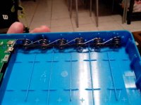
Anyways... I'm still working on that battery, but today I tried it on my bike (without a BMS and the celllogs that I plan to install) and it was Fun (50 km/h easily). The goal of my post is to share my battery build progress... And since laptop cells sometimes fail, I wanted to avoid soldering cells. I build everything from Plexiglass (2.5 mm thick acrylic sheets). I flattened copper pipe and drilled them to make bus bars, and used 211 D battery spring (from digikey.ca) and brass nuts and bolts (from Reno depot) for battery contacts.
But images tell more than word…