(Another) pre-charge circuit?

jkrienert

100 W
Joined
Jun 13, 2021
Messages
120
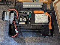
Hypothetical pre-charge sequence for a 84v traction pack, HV contactors (p- w/resistor, m-, m+), HV:LV (84)dc:dc(13) converter, 12.4v accessory battery, and two LV amplification relays. Presently working on the wiring diagram for all this, so some help in elucidation is pending...

Sequence:
  1. OFF - All relays and contactors are open. No HV leaves the traction pack box that contains the battery modules, dc:dc, and HV junctions.
  2. PRECHARGE - Press a ST momentary switch (electrical choke) to connect the 12v accessory battery to a single LV amplification relay that drives both pre-charge contactors (-p and +).
  3. PRIMED - The (84)dc:dc(13) converter is unswitched on the pre-charge (and main) contactors output. So, once its input capacitor is saturated from the pre-charge (2.) an unswitched resistor and LED on it's 13v output illuminate, indicating the HV system is primed.
  4. HV ACTIVE - While primed (holding choke or while capacitors hold charge), dc:dc(13v) output to the ST key ignition is open, and when turning the key to close (start) power is sent to the main contactors (-, +).
  5. HV USE - while key ignition is closed a LV two-way latching toggle switch determines the route for 13v power to the contactors for discharge or recharge that has a third LV+ relay for the charger interlock.
  6. SHUTDOWN - Whenever key ignition switch is re-opened (off) the two main contactors open and the HV traction pack returns to isolated state (1.).

Hopefully... having the pre-charge governed by an accessory battery on isolated LV+ from the dc:dc output prevents the traction system from being active without the 'choke' pre-charge sequence. Ideally, this method also automatically cascade opens all HV connections inside the traction packs case if any interlock or fuse on the dc:dc is triggered.

Conceptual or applied improvements?

EDIT: Now seeing that having the key ignition closed to charge is, far from ideal. Need to revise that LV+ circuit path...
 
Last edited:
Well, choosing an alternate BMS with those capabilities would be cool. It would require I redesign several parts of the build.

I am working with 2nd hand OG Orion in 32S format, and a repurposed Prius HV junction box (where the -p, -, + contactors live).

Do you have any 32S capable BMSes with pre-charge options you'd recommend?
 
Last edited:
Do you have any 32S capable BMSes with pre-charge options you'd recommend?
I have a model from ANT in my CRF, and I'm quite happy with it. It's a Chinese brand but the app is quite decent, there's some documentation, they have options up to 32S and they're very well priced. Quite a few people on the forum have used them with success, AFAICT.

When I'm working on my bike, I can remotely disable the battery (charge and discharge sides separately) and make or remove connections. Once I'm happy with everything, I simply turn the discharge back again and it automatically precharges everything, and it's been remarkably uneventful so far. Having it wireless has another benefit that my battery only has two sealed holes for the main connectors, as you might have noticed in my thread. The BMS has a physical enable switch if you turn it off completely (e.g. to save power during longer storage) but I've wired a reed switch to "click" that line without a need for an extra cable. CAN would of course require another pair of connectors, though.

This entire setup means I don't have to run heavy, expensive contactors, large fuses and complicated precharge interlocks, since the precharge is effectively powered from the battery itself.
 
Well, @bananu7 your post gives a lot of excellent help. It certainly leaves me with a sense of "...oh wow, I overbuilt this."

I might follow through with what I've got on hand, since most is here ready to culminate. However, I am also hopeful that this build will work out well enough, that someday I can build another. In that case, with gravity towards some of the methods you've been implementing and shared. Thanks for that!
 
In a "but wait, there's more!" moment, one extra thing that it allows for is setting a custom charge cutoff voltage if you e.g. don't have the appropriate charger, don't trust it or simply want to charge the battery to a lower voltage (e.g. 4.1V per cell). In my observations, it's actually the BMS that stops the charging, not the charger itself.
 
That definitely elevates the value of that BMS.

I'd planned to use the Orion's user-settable LVC and HVC. The HVC will monitor a relay governing the (Quiq) Charger's trigger. That is a backup, since this charger has a programmed algorithm for this pack (32s SCIB LTO, 2.6v = ~83.2).

If you'd pondered based on cell chemistry, weight isn't a critical factor in this build. Though, I just looked at the dimensions of the ANT 32S and good gosh... That would free up >300% the volume inside the alum traction pack case, by removing the contactor assembly and OG Orion. That would be enough room to move the planned external 13.8v accessory (lights) pack, into the same case as the traction pack.

Hmm....
 
Last edited:
How many amps are you planning to run?
If you want to really overbuild it, use an Arduino or similar to control the logic for the relays so nothing can blow up. User just needs an on/off switch. Then you can do things like preventing the main contactor from closing with a shorted load and sequence the relays properly.
 
I'm overbuilding for safety and learning sake since it's my first ev project. Though, in that I'm also underutilizing the LTO cells capabilities.

The cells were purchased from BHook, and came with laser welded tabs rated for 40a. Since the 32s cells are 2p they could handle around 80a. If those tabs were more robust they could probably handle a lot more... Anyway,

The cells power cycle is limited by the controller I have. This came paired with a hub motor, neither of which I'll be able to upgrade until I can verify the traction pack is working. This generic controller is rated at max 40a, which I'm supposing is battery amps.

So at nominal voltage from the 32s2p pack, it's only going to top out around 3kw through the contactors, which are rated for more, around 20kw based on what I researched about the Prius traction pack (220v).

As i become more knowledgeable working with these slightly older parts, I can evolve the power delivery to get closer to these cells capabilities around 6-7kw, maybe short bursts around 10kw if I can design a decent cooling system.

@fechter , Using a logic controller is a novel idea, thanks for sharing that notion. I've done quite a bit of VB and Python coding, so the learning curve might not be too bad. Being able to check for load shorts is an awesome capability. Sounds like that would certainly add another level of safety, and simplicity for the rider(s).

All that said, I've been 'brushing' this pony for 3+ years now with little free time here and there, so I'm really driven to get it driving, especially since spring and summer are returning to my latitude. Integrating a logic safety control system next winter when it's back in the 'stable' is starting to seem like a todo the more I consider it, rather then just a possibility...
 
Last edited:
For that voltage/current level, you could use FETs instead of mechanical relays. Smaller and way less standby current draw.
 
Do FETs fail open?
If not, I'd maybe rig an economizer on each contactor before replacing with FETs - if an economizer would save some comparable amount of power as the FETs. I'm not an e.e. so I honestly don't have a tremendous understanding of those components ratings. Do you think economizer parts might be around the same cost?

Though, not all have to be FETs right? I wonder if a hybrid could work, highest potential main + a contactor, then FETs for the (-p) and (-)...

Also, for the discussion in point, the two main contactors and 12v drive relay combined draw about 0.7A without economizer so, around 8w of the 2.5kw pack. Neither a little or a lot I suppose. To me it's an acceptable amount of loss to feed the horse, and I don't mind feeding once a day, which is about what this pack will require for my uses. Even if I feed (charge) it twice a day and the cells don't have an anomaly, it will still last a long time given the chem.

Though I agree @fechter , striving for efficiency is worth it.
 
Last edited:
Do FETs fail open?
Typically they fail shorted.

If the short is in a very high current system, they may explode and vaporize enough material to open the circuit.

But in many applications they don't do that, and the failure (even with fractured cases and plasma escaping onto nearby components) is usualy a low-resistance short. That's why in motor controlller failures it's common for the motor itself to be harder to turn than it should be, as the phase windings are shorted together via the blown (shorted) FETs inside the controller.
 
Typically they fail shorted.
That leaves me concerned about using them for the traction packs isolation.

In the case of a low-resistence short, is the consequence you described equivalent to the back (3phase hub) wheel locking up, potentially at speed?
 
Last edited:
In the case of a low-resistence short, is the consequence you described equivalent to the back (3phase hub) wheel locking up, potentially at speed?
An actual lockup is unlikely unless all three phases short, but two phases will give quite a bit of drag.

The more torque the motor itself can produce (regardless of what the controller can supply it when working), the more drag it will create when shorted.


At least it's not as bad as a brushed motor controller, which fails *stuck on full output* when it's FETs short. :/ Those you'd have to have some kind of emergency pull-disconnect for the battery/controller connection, or a mechanical brake on that wheel that's good enough to stop it even under full power while moving down the road at full speed, and a fuse from battery to controller that will blow as the current draw becomes greater than normal before the motor burns out from the braking-under-power.
 
But the contactor isn't going to prevent a controller FET short from locking up the motor. Normally you wouldn't put any kind of switch between the controller and the motor.

But as a contactor, yes, FETs tend to fail shorted, so may not be as safe as a mechanical relay. The power wasted by the relay coils will be pretty small compared to the motor, so as long as you don't forget to turn it off after riding, it won't be significant. An automatic time-out could be another feature for the microcontroller.
 
@fechter I might have worded something odd, since I am not planning any switching (contactor or FET) between the motor and controller.

My contactor/relay/FET design dilemma is all before the drive system, on the HV traction pack output.
...
@fechter I hope to remedy auto turn off of main HV contactors when the ignition key is removed.

The goal is to only close the main HV contactors* from the LV output of the DCDC converter connected to them*.
The only way to start that main HV circuit is by momentarily supplying a LV 'jump' via 12v accessory battery to the pre-charge contactors. That temporarily closes the HV circuit and activates the DCDC, that then closes the main HV contactors as the pre-charge opens. The main circuit has several safety's inline (ignition sw, inertia sw, interlocks, e-stop) that cascade open all LV supply to main contactors.

That last bit is probably the main challenge, sufficient jump time to alleviate HV in rush, while also having enough capacitance or overlap of the pre-charge and main contactor activity that the self sustaining main contactor and DCDC don't drop out and require another pre-charge iteration. I have hopes of doing this with basic components, yet perhaps this is when a microcontroller might be a big help...

I need to post a diagram soon. That will probably help a lot to describe what my technical words might be lacking.
 
Last edited:
Draft wiring diagram added...
 

Attachments

  • _draft_hv_junct_main_bus_diagram.png
    _draft_hv_junct_main_bus_diagram.png
    116.1 KB · Views: 14
That last bit is probably the main challenge, sufficient jump time to alleviate HV in rush, while also having enough capacitance or overlap of the pre-charge and main contactor activity that the self sustaining main contactor and DCDC don't drop out and require another pre-charge iteration. I have hopes of doing this with basic components, yet perhaps this is when a microcontroller might be a big help...
555 timer is easy, or integrating op amp (which is already inside the 555). if you need more than one timeer they make two in the 556 or four in the 558. bajillion circuits and calculators for these chips out there
 
While a 555 timer is indeed very easy for very simple circuits, the cost and availability of small microcontrollers means that one can now build much complex systems with them with relative ease. And programming them is also easier now.
 
I'm not sure I'm following everything in the schematic, but I see one contactor for the precharge, and two additional contactors. Normally I'd only use one because they're big, heavy, expensive, use signficant power and are a potential failure point. One is enough to break the circuit.
Are the terminal labeled 72v bus where you're attaching the motor controller?
 
@fechter - yes these contactors control the main 72v bus where the controller connects. That connection is shown in the lower left of the diagram, though I didn't annotate the controller there yet ...
EDIT: those two bus points are in the center of the HV control system shown in the photo below, two m6 bolts between the left HV junction, and right, BMS.

The three contactors with busses are all nicely housed in a Prius HV junction box. For the record , you can find outstanding deals on these contactors modules from salvage yards. The one I'm working with was $30, and the components show no signs of failure.

These contactors don't have as good an HV rating as some of the other expensive ones out there, but their designed for the Prius 202Vdc battery, so plenty of headroom for this 83Vdc build.

Two contactors are the battery mains, one for the positive and one for the negative. The other contactor is negative with a resistor for lower relative pre-charge current. The positive contactor is used in both main and pre-charge sequences.

During either stage (2 contactors and 1 drive relay) the max draw is around .8A at 12v. That isn't a huge chunk of the main battery capacity, and easily replenished during daily recharge. I've selected these contactors after starting the design with just 1 on the positive HV, which evolved to multiple to protect components and as a precaution for regulations on safety systems for HV supply (>60vdc).

A picture of the HV junct and BMS in the case might give some helpful context. You can also see the controller which will be mounted to the top of this half of the clamshell case. The open area at the bottom of this half shown, and the entire other half (not shown), is where the traction pack modules will be mounted. The modules ONLY HV HC connections are the two orange 8awg lines on the image left. The positive (top) goes through the DHAB current meter, and negative goes strait into the junction box. The interconnect between the traction modules is an SB50 and two 8awg lines on the right side of the case.
 

Attachments

  • PXL_20250307_200654516.jpg
    PXL_20250307_200654516.jpg
    3.1 MB · Views: 9
Last edited:
While a 555 timer is indeed very easy for very simple circuits, the cost and availability of small microcontrollers means that one can now build much complex systems with them with relative ease. And programming them is also easier now.
True, but it's hard to get feature creep with a 555 type design. ;)
 
I'm all for using available materials, especially when the price is right.

What are the squares with "in, out, gate, norm open"?

Personally, I would avoid using a pushbutton for the precharge. Too much chance of something getting switched out of sequence.
Also, did you test whether you can precharge with the DC-DC attached? The converter will draw something and have some drop across the precharge resistor. The precharge resistor should probably be the lowest value you can use without exceeding the contact current rating on the contactor.
 
What are the squares with "in, out, gate, norm open"?
lunch break -

Those symbols are the LV amplifier relays, automotive grade or in my case the ones from a salvage fuse box, ~12v 20A, from a 2015-2018 GP Renegade INt. Fuse Relay Box 51975322 OEM.

I've not tested the DCDC yet. Maybe relevant mention, it has a HV input capacitor, el. cap 100 uf 450V.

As far as I can tell, the resistor in this HV junction box is propriety, not as off the (salvage) shelf to replace. Interesting to find this box does pre-charge on negative path, leaving a single, relatively always on if on, +positive contactor. I'll be using that system.

Far as resistor goes, my search engine (T. P. 03842-48020 BGR30TQS) image deciphering; squints eyes, suggests ~20ohm ?w. I also gave it a measure with the meter, 29 Ohm. Maybe 200-500w based on size (8ccm) and original battery (202vdc-40A)?.

Far as working for this build, that resistance with the voltage 83v. and 2600 uF capacitance to fill, precharge is ~0.345 sec. based on this online calculator (didn't verify yet, https://www.sensata.com/calculator/precharge).

Hope to test the dcdc soon, just need find some time.


1744050575615.png
 
Last edited:
Back
Top