Aotema brushless contoller questions

ekingsting

100 mW
Joined
Jan 27, 2009
Messages
46
Location
So. Cal
After logging 400 FUN and trouble free miles with my new brushless Aotema I went for a 10 mile ride yesterday and 1 block from home the motor quit running while at 2/3rds throttle. The motor and controller were barely warm. Failure occured as I rode over a manhloe cover (small bump), the power to motor stopped instantly. No pop, smoke or burning and all led lights still on throttle and controller. When throttle is activated the green light on controller flashes 4 times repeatedly as a code.
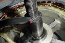
Opened contoller- no visible damage. Pulled front hub and found 1 phase wire had a small v shaped cut out of the insulation at axle slot. Found small burr on edge of axle shaft wire slot. The wire harness was secured tightly and motor axle has not ever spun- have torque arm. Note to anyone installing aotema hub- push protective phase wire sleeve all the way into axle slot to prevent chaffing of wires on edge from road vibrations. I repaired wire and tried controller again - no motor power. Next I tried a different throttle still no motor power.
What does flashing code mean? New controller ?
 

Attachments

  • DSC00231.JPG
    DSC00231.JPG
    188.9 KB · Views: 4,318
If you measure resistance between every phase (yellow/blue, blue/green, green/yellow) do they all have the same resistance ?

Did you measure resistance on the mosfet between the drain and the source pin...to make sure none of them are shorted (damaged) ?

Do you get output on every hall signal (are output changing while the wheel turning?


Robin
 
Thanks for your help Robin. The phase wires ohm the same . As a newbie to circuit boards I'm not sure how to check the mofset but I will figure that out and post. There are no hall sensors in motor.
Here is a picture of a bunrt part found on smaller circuit board in controller . Is this possible to repair ?
 

Attachments

  • DSC00233.JPG
    318.4 KB · Views: 4,317
ekingsting said:
. As a newbie to circuit boards I'm not sure how to check the mofset but I will figure that out and post.


Just find the big trace that go to the mosfet, there will be 2 big trace that go to 3 Mosfet it will be the GND buss or the + Bus (if it's a 6 mosfet controller) and there will be 3 big trace that goes to each phase wire...


There should be no conductivity between any of these big trace(between the 3 phase and + or - bus)....if there is, then you have a shorted mosfet.

Robin
 
That little board does the sensor simulation. It reads the back EMF from the motor and creates sensor-like signals. Not sure why it would get damaged. Where did you buy the motor? If you got it from Hightekbikes, we will repair or replace the controller for free.
 
Update- the fets check out ok, thanks for the help Robin.
Terry-I bought the kit off ebay in Dec. so no warranty but I greatly appreciate your concern and offer to solve my issue( new hub kit buyers take note- BUY from some one who will be there to assist and warranty- any small extra cost will be worth the money. The timing circuit burned when phase wire shorted against axle at cut pictured in first post..
SO I decided to resolder burnt fuse link( not sure what it is) back onto circuit borad and I am happy to report a successful 1 mile test . OK for now but I will post if problems arise.
A BIG thanks to all on the forum
 
the blue coated wiring is nearly cut through all the way through. My green wiring is ok. some of the green insulation is pinch and sliced but the aluminum wiring appears. What could have happened is that it's streched or damage inside the hub. Plus 48volts demands more than 36v. everything has to be tip top.
 
on your sensorless feedback pcb, it looks like that surface mount resistor fried when the phase wire shorted. that was nice of terry to offer to fix it. they are not easy to solder back on but it can be done. maybe terry can look on one of his pcbs and tell you what the resistor value is and you can find another. if there are several identical traces like that for each of the phases, then you might assume that the resistor is the same as on the other traces. you might even be able to just find a small 1/8W resistor and solder it down along the trace, but i bet the balance is critical so measure with an ohm meter to verify they are within 1-2%.
 
I'm not putting another controller on mine until I'm sure the hub wiring is right. I'll send the hub out fed ex if needed.
 
RTLSHIP said:
the blue coated wiring is nearly cut through all the way through. My green wiring is ok. some of the green insulation is pinch and sliced but the aluminum wiring appears. What could have happened is that it's streched or damage inside the hub. Plus 48volts demands more than 36v. everything has to be tip top.

When I opened my hub, easy to do just follow Dogman's instruction on an earlier post, I did not find any problems inside with the wiring. I believe the road vibrations slowly caused the cut even though the harness was very secure. Also the black protective covering is not installed far enough into axle to protect wiring. The axle shaft tunnel has very sharp edges!
 
I had had this exact problem with a WE bl-36, fortunately my vendor was awesome and sent me a new controller. For your reference, this is what the controller light patterns mean:

From my WE documentation:

Red light = power (on/off)

Green light blink codes:

steady = all connections correct, no signal from throttle

No blink = motor is receiving throttle signal and power, motor should spin

Slow 6-blink pattern = hall effect circuit disconnect/broken wire

slow 8-blink pattern = batt voltage below 31.5v - RECHARGE! (their emphasis, not mine :) )

Slow double-blink = brake cut-off circuit is engaged

light blinks while motor is powered = trouble with the hall effects circuit
 
That resistor value is 680 ohms. It was the same problem I fixed for my customer. You can solder on a thru-hole resistor. From what I can make out so far, this is the input from the 12V bus on the controller. This resistor along with a zener diode forms a shunt regulator, probably 5V. So 12V --> resistor --> zener diode to GND. That's only about 17mA, so I am not sure why it is frying but I think it's related to the back EMF from the motor being a higher voltage. What surprised me about this board was it consisted of a couple LM339 comparators...no processor! Should be relatively easy to reverse engineer and tweak.
 
My customer fried this board again. This time two mosfets got fried also. I'm still creating a schematic for this board but the main part has the motor phases going to a 100K resister then a 2.2K resister, then to the LM339 comparator input. There are two caps to GND forming a low pass filter to eliminate glitches. Doing the math, at 50V input, the current is only 0.4mA. So I am at a loss as to why the higher voltage is causing the input regulator to burn up. As a reminder this is a zener diode shunt regulator. The resister part of this is 680 ohms and is the part that burns up. The zener seems to be about 9V but I have to verify this on a known good unit. There is little or no filtering on the 12V input, so I don't know what this looks like in operation. Is the LM317 loosing regulation, passing full voltage? I will have to monitor this with a scope. The only hypothesis I have now is that the LM339 is latching up somehow and drawing huge amounts of current, more than the resister is rated for. And what fried first, the sensor board or the mosfets? What happens if the sensors put out the wrong signal? Would the processor turn on the wrong mosfets, creating a short? More to come.
 
is the 9V zener in series with the 680R surface mount? that could be a latch to prevent the phase wire signal from climbing too high for the op amp input. i assume the signal is taken off the phase wire through that resistor ladder bridge and that is the input to the op amp acting as the comparator. but the op amp input would need to be protected from input voltages above the 12V rail it runs off.

that make sense?

if you can pull up the output of the regulator LM317, to say 15V and then raised the zener to 14V or so then that would reduce some of the spike, and then see if a 2-3W power resistor could fit on the trace, and reduce the value to say 200-300R. i don't think there is space for it though, maybe just solder another 400R 1/2 W right on top of the 680R surface mount, and see if it will run with the 9V zener then. little steps is easiest i guess.

the blown FETs could be a clue if they caused the sensor resistor to blow up when they went out.
 
Very strange- Went for a ride this morning and fried controller again. I was going slightly downhill on a very rough paved road at 34mph for less than 45 seconds at full throttle and I let off throttle quickly to avoid pothole. 5 seconds later I applied throttle and nothing. Burned sensorless board resister again. Both failures have occured after short full throttle runs ( less than 60 sec.) on a rough road and quickly releasing throttle. First failure at 450mi and second at 750 mi. Maybe it does have to do with back emf.
Terry, what is your customers story about at time of failure?
 
why would letting off the throttle quickly be different? that is what is curious, but i agree it seems like the voltage on the sensorless board is too much or maybe a bigger resistor there will help. do you think you could fold the legs of a leaded 1/2W resistor underneath itself to sit on top of that surface mount resistor? a small wirewound would be the best but they are big.

if you guys can get good pictures of the layout maybe richard or jeremy could figure the circuit.

was the white stuff on yours meant to cover it up? can you get images of both sides?
 
I'll keep posting as I find stuff out. The LM339 is a comparitor, not an opamp. My customer was also going down a slight hill at time of failure. This could be a clue as I have had other controllers burn up due to excessive back EMF (regen). Let off the throttle going down a hill and the motor becomes a generator.

You could be right about the voltage at the input to the comparitor rising above it's power rail, causing latchup. Who knows what the voltage spikes are coming off the motor. Adjusting the voltage supply to the comparitor might throw off the switching thresholds but is worth a try. I'll keep tracing out the schematic as time and patience permits. I'll get some pics tomorrow. The two mosfets that blew were in parallel on the same phase.

The part on the sensor board that burns up is the series resistor for the shunt regulator. This is the power supply for the chips. It is not related to the input circuit that connects to the motor phases. It is a surface mount 680 ohm resistor, and is acting like a fuse. A thru hole resistor can be placed on the board with double sided sticky and connected to the pads with wire-wrap wire. When a fuse blows, you need to find out why, not put a penny in the socket.
 
Here is the latest on my second controller failure. I decided to open up hub again and investigate even though I have 100mi. on a different style controller(smaller7 fet model) no problem so far. Found blue phase wire had apparently grounded momentarily to axle thru small cut in black protective cover. This is new as the last cut was removed. I don't know how grounding the phase to axle would blow controller mircro board resistor. Any Ideas or comments on this would be helpful.
 

Attachments

  • DSC00255.JPG
    DSC00255.JPG
    53.1 KB · Views: 3,383
  • DSC00256.JPG
    DSC00256.JPG
    35.8 KB · Views: 3,380
  • DSC00257.JPG
    DSC00257.JPG
    38.9 KB · Views: 3,381
  • DSC00258.JPG
    DSC00258.JPG
    38.3 KB · Views: 3,382
7 FET model, whoa!!! you mean six plus 1 other part. either a voltage regulator or transistor used for supplying 12V rail.

so it ran with the cut on the wire while you used the 6FET controller, but not with the other one? that blew up?

this is the aotema sensorless controller with the blown resistor on the sense feedback circuit, right?

i don't think that nick could do much if it has no return path for the current and it was just that nick.

i don't see how it could put a voltage spike on the sense wire too, which is what appears to overwhelm that zener, as i recall.

so i think the nick and failures are different, unless maybe there are other nicks and two phase wires short, but you would know that if it happened.

edit: but it could be related, see if the blown sense wire is from the blue phase wire
 
dnmun said:
7 FET model, whoa!!! you mean six plus 1 other part. either a voltage regulator or transistor used for supplying 12V rail.

so it ran with the cut on the wire while you used the 6FET controller, but not with the other one? that blew up?

this is the aotema sensorless controller with the blown resistor on the sense feedback circuit, right?

i don't think that nick could do much if it has no return path for the current and it was just that nick.

i don't see how it could put a voltage spike on the sense wire too, which is what appears to overwhelm that zener, as i recall.

so i think the nick and failures are different, unless maybe there are other nicks and two phase wires short, but you would know that if it happened.

edit: but it could be related, see if the blown sense wire is from the blue phase wire

Dnmun, yes it has 7 fets as you can see but I did not check tracer yet as it is installed on ebike, and yes it has run for a 100mi of very easy riding so far no bad roads. As far as the wire it would only touch axle under heavy vibration even though the harness was very secure.When checking resistance thru phase wires with hub together it would read .001ohm then jump all over between .001 and9.00ohm and never steady if wire moved. With harness free of axle in opened hub the phase wires read steady .001ohm even while moving wires. I am going to remove sharp edges with dremel. Terry has my controller for modifying, so can't check where sense wire is. Only one phase was nicked as far as I can tell now - will inspect further.
 

Attachments

  • DSC00260.JPG
    DSC00260.JPG
    77.1 KB · Views: 3,365
maybe just squirt silicone rubber through the outer sheath and rotate the nicked wire with some silicone covering the nick just a little to get behind the continuous part of the sheath and then heat shrink some silicone right over the entire bundle and axle end with silicone inside to squeeze out into all the voids as the heat shrink comes down in size. like a splice in direct burial.

all the phase currents are totally isolated from the bike frame which is isolated from ground even, so it seems a no op in your controller problem.
 
What's the voltage maximum on that controller? I just bought the same 48v controller f/ camp- solutions. This was ekings idea.
I see something in the picture that says 50 v. Hopefully, this controller will endure.
But there is a loss of flexibility as this controller cutsoff @ 41 or 42. no more 36v packs.
The price isn't bad at $49 and a 48v thumb throttle is included, but the shipping was $15.
ekings 100 miles with no problems is good. My voltage will be a little higher. 59v
 
Just make sure the phase wires are well protected ( and secured from vibrations) as they exit the axle. The axle has a sharp edge and will cut thru wire cover and possibly cause a short that could damage controller.
 
ekingsting said:
Just make sure the phase wires are well protected ( and secured from vibrations) as they exit the axle. The axle has a sharp edge and will cut thru wire cover and possibly cause a short that could damage controller.

Thanks for that. Will duct/insulation tape do the job? Thanks again. :mrgreen:
 
Back
Top