
I will try to get some. I was having issues with bad solder joints so I changed to a bolt to clamp the fet legs and the caps to the buss bar for prototyping. I can tell you this has not been an easy or cheep journey every time a fet blows I take out all the buffer fets and the drivers and a couple times the dspic chip too! Twice I have had > $200 with of stuff and about 6-10 hours of time all at once. I am really thinking its time for some isolated fet drivers.. I have spent the whole weekend working on this and found so many wrecked things from trying just 100v a couple days ago. I really see the advantage to the TI safety boards, you can short two phases out and it will protect it self. Maybe mine well too now that the Hi side fets are electrically isolated from the bus bar. Well back to the shop to see if I can get it running today.
You are using an out of date browser. It may not display this or other websites correctly.
You should upgrade or use an alternative browser.
You should upgrade or use an alternative browser.
Arlo's power stage Leaf controller runs and drives page 103
- Thread starter Arlo1
- Start date
OK.... WHERE do I head from here?
I spent the night tring some caps on the Drain to source while I scoped the gate to source...
And shit as I typed this I remembered I need to change where my scope ground is lol. I put the scope ground on the phase wire. But the scope ground needs to be at the fet which is about 12 inches less inductance to deal with and make the screen look better.
Ok so here is some pictures but I used a 3300pf Ceramic cap and I added resistors to it in series. But here is the thing with just the cap across the drain to source of the Low side fet the Hi side fet gate in the same H bridge looked better BUT and I SAY BUT the cap gets HOT FAST then when I added a 6.8 ohm resistor in series it looked worse and the resistor got hot so fast I bunt my fingures in the time it took to push the stop button on the scope. So I tried 2 6.8ohm resistors in parallel then 2 more 1 ohm resistors in parallel and they all got hot, hot enough if I hold them there they burn my fingures.
I also tried various caps on the bus bars to try to help the situation and a couple did make a very small difference.
I will look more at it tomorow but I am up for sugestions!
BTW my probes are on 10x scale and im not sure why it reads 10x off on ultrascope
All power is from a charged 12v lead battery ATM.
Attachments


It's important to put the ground and signal clips close to where you want to measure. If there are high frequency signals in there, you also need to minimize the inductance of the ground wire of the scope. You can do that by loosely twisting the standard scope ground wire around the probe, or better, by twisting a bare wire around the ground connection close to the tip of the probe.
Pictures:
http://koti.mbnet.fi/jahonen/Electronics/Stuff/Probing-Example.jpg
http://electronics.stackexchange.com/questions/40420/what-is-the-name-of-this-springy-type-oscilloscope-probe-accessory
EDIT:
About the snubbers. They will dissipate heat yes. If you put one on the high side, and one on the low side, they will work better, and maybe you can use smaller caps (less heat). Put them right at the FET legs, and use short wires.
Lebowski
10 MW
Read the post I made about snubbers, and remember to measure between drain and source ! NOT GATE AND SOURCE !!!!! don't just mess around with caps and resistors, take the scientific approach and calculate them. Fix the drain- source side and the gate source will improve automatically. To measure drain source, measure between the motor terminal and ground, as close as possible to the fets. The ringing after a rising edge must be fixed with a snubber on the low side fet, the ringing after a falling edge with a snubber on the high side fet. The snubber are not necessarily equal.
OK So.... I went and scoped for about 2 hours and every time I went to leave the shop I was thinking oh one more thing lol I went back and fired the computer/scope/controller up about 5 more times to gather as many tests as I can.
First thing is the gate on the low side is held under a LOT better control with a shorter inductive loop. I only have the jumper from the Hi side source to the last buffer fet source leg attached on one of three driver boards and I scoped that one and what do you know when scoping source to gate its not so bad! I will have to re-install the other two jumper wires.
First thing is the gate on the low side is held under a LOT better control with a shorter inductive loop. I only have the jumper from the Hi side source to the last buffer fet source leg attached on one of three driver boards and I scoped that one and what do you know when scoping source to gate its not so bad! I will have to re-install the other two jumper wires.
Attachments

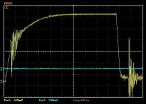
Next I scoped drain to source on one fet and the gate so I could try 0 dead time vs 500ns dead time and the 0 dead time was no advantage. I did this because of what Tehstork has mentioned in his thread and on lebowski's setup thread. It may look a touch different but its just my fault I had the zoom different for the two screenshots.
Attachments


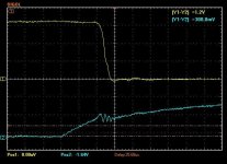
Ok so here is the ringing from Hi side drain to source with one probe and the other probe on source of the low fet. Done at 12v for now but aiming for 170v (just can't run 170v untill this is fixed....
Hu?? Can someone walk me through this. And What Factor (scale) are the cap numbers for this formula?lebowski said:- calculate the impedance of the capacitor at the new (lower) ringing frequecy using X = 1 / (2 * pi * f_new_ring * C_snub)
- the snubber resistor should be taken as 1.5 times the capacitor impedance X.
Now the only thing to watch out for is the power dissipated in the snubber resistor. This is given by:
P_snub_r = f_pwm * C_snub * (V_bat)^2
First put snubbers between all drain/sources of the FET's (see also attached picture where the snubbers are the 4.7 nF and 6.8 Ohm components)
After this is done, look at the gate / source signals. Chose the gate resistors such that there's no significant overshoot which can
blow the gate oxide. Im my controller I didn't need gate resistors, the gate signals looked nice and clean after snubbing the drain/source's.
If the drain/sources are not snubbed the ringing will 'transfer' to the gate by means of the Cgd, this is what you're seeing.
Attachments
-
 Capture Negative on source positive on drain hi side and other probe positive on oposite fet s...JPG48.6 KB · Views: 2,269
 -
 Capture Negative on source positive on drain hi side and other probe positive on oposite fet s...JPG51.1 KB · Views: 2,269
 -
 Capture Negative on source positive on drain hi side and other probe positive on oposite fet s...JPG50.8 KB · Views: 2,269


So from lebowski
- calculate the impedance of the capacitor at the new (lower) ringing frequency using X = 1 / (2 * pi * f_new_ring * C_snub)
So X = 1/(2 x 3.14159 x 1,500,000 x .000001) ->-> X = 1 / 9.42577 ->-> X = .10609
What does this meen?
How do I determin what caps I need? if I want 1/2 - 1/3 of the original ringing frequency. How do I know what caps to order?
And Is this going to work even though Im testing at over 10x lower voltage then I am planing to run?
Edit: I found this app note http://www.nxp.com/documents/application_note/AN11160.pdf
I calculated Circuit inductance Llk= 10nH
and Circuit capacitance Clk = 13164.82pF
so with rining at 13.51 Mhz I need a 27 nF cap and .4357752 ohm resistor in series to get a "critically damped” circuit!
Lebowski
10 MW
No, you need 39nF (3 times the cap that's already there). This will bring the total cap to 39nF+13nF=52nF. With the 10nH inductance the new ringing frequency will be 1/(2 * pi * sqrt(L*C) ) = 7 MHz. The resistor you need is 1.5/(2*pi*7e6*39e-9) = 0.9 Ohm ( don't forget the 1.5 !), best build using 3 2.7 ohm resistors in parallel. Use low inductance resistors!
A big thing though is that you're not using the final voltage... if you look at fet datasheets at the Coss graph you'll see that it's supply voltage dependent. If you're going to run at 160V I'd measure and calculate the snubber at around 100V. You'll see that the snubber capacitor will be a lot less, and the resistor a lot higher. Lower snubber capacitor is good as it reduces the power dissipated in the snubber.
A big thing though is that you're not using the final voltage... if you look at fet datasheets at the Coss graph you'll see that it's supply voltage dependent. If you're going to run at 160V I'd measure and calculate the snubber at around 100V. You'll see that the snubber capacitor will be a lot less, and the resistor a lot higher. Lower snubber capacitor is good as it reduces the power dissipated in the snubber.
I can't test at 100v untill I get it to quit bloing up last time I hooked 100v up it cost be 150-200$ in blow up shit!
I am making huge progres though.
So I have a little data from tonight and I will try soldering snubbers on 6 phases tomorow.
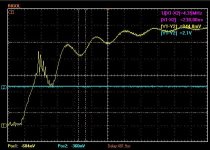
Here is some data. I held a .015,.022,.033, and a .015 in series with a .033uf cap on drain to source of the low side fet and scoped the hi side source to drain. I then tried .5 ohms in series with the cap and I think the resistance made it worse. But I did only have presure to make it conduct and not solder. It was also only one side of the H bridge. It did make it way better and .033uf seemed the best.
Edit: Just realized I was looking at the wrong part of the wave.... The hi side (mesured part) looks awesome when it goes low because thats when the low side turns on and puls it low. .033uf and .5 ohm look best so far. I will try more tests in the morning! Super stoked!")
I am making huge progres though.
So I have a little data from tonight and I will try soldering snubbers on 6 phases tomorow.
Here is some data. I held a .015,.022,.033, and a .015 in series with a .033uf cap on drain to source of the low side fet and scoped the hi side source to drain. I then tried .5 ohms in series with the cap and I think the resistance made it worse. But I did only have presure to make it conduct and not solder. It was also only one side of the H bridge. It did make it way better and .033uf seemed the best.
Edit: Just realized I was looking at the wrong part of the wave.... The hi side (mesured part) looks awesome when it goes low because thats when the low side turns on and puls it low. .033uf and .5 ohm look best so far. I will try more tests in the morning! Super stoked!
Attachments
Lebowski
10 MW
Arlo1 said:The hi side (mesured part) looks awesome when it goes low because thats when the low side turns on and puls it low. .033uf and .5 ohm look best so far
No, its the other way around. You measuring across the high side FET (which is a weird way to measure but it is OK, I always measure between ground and the output terminal), so when this goes low it means the high side FET turns on (shorts where you measure with the scope). This fits with the snubber being on the low side FET, a snubber is active when the FET it is in parallel with turns off.
About measuring at 100V, did you try this with the PWM test feature without any load ? The 33 nF you're using is very high, a high Coss (FET output cap) is caused by the low supply voltage. When you go to 100V the dissipation (see equation I posted) will be around 7W per snubber, 17W at 160V ! It's better to re-measure at 100V and go for the lowest cap possible, a cap that reduces the ringing frequency by a factor 2.
P.S. at the bottom of your scope its saying the trigger point is 440u-sec away, don't traces jump around a lot ? Isn't it easier to trigger close by ?
Last Time I hooked 100v up I clicked the PWM test mode and the second I pushed enter the controller exploded into plasma!Lebowski said:Arlo1 said:The hi side (mesured part) looks awesome when it goes low because thats when the low side turns on and puls it low. .033uf and .5 ohm look best so far
No, its the other way around. You measuring across the high side FET (which is a weird way to measure but it is OK, I always measure between ground and the output terminal), so when this goes low it means the high side FET turns on (shorts where you measure with the scope). This fits with the snubber being on the low side FET, a snubber is active when the FET it is in parallel with turns off.
About measuring at 100V, did you try this with the PWM test feature without any load ? The 33 nF you're using is very high, a high Coss (FET output cap) is caused by the low supply voltage. When you go to 100V the dissipation (see equation I posted) will be around 7W per snubber, 17W at 160V ! It's better to re-measure at 100V and go for the lowest cap possible, a cap that reduces the ringing frequency by a factor 2.
P.S. at the bottom of your scope its saying the trigger point is 440u-sec away, don't traces jump around a lot ? Isn't it easier to trigger close by ?
I have an issue with the hi side turning on from the loop inductance, when the low side turns on. Although the diode on the gate resistor and the jumper from source to the last buffer fet helps its not curing it and the snubbers will be needed.
I will try some tests at 50v and see what snubber works best. The calculations from the link I posted don't use voltage for the equation so.... But maybe I will get lucky and .015 or less will be the ticket.
? The cap charge alone is enough to blow a fet during passthrough!circuit said:So simply connect a 100Ω resistor in series to B+. Or a light bulb (the old style one).
So lower the cap. You certainly don't need all those farads to simply check it no-load. It's a common practice in power electronics.Arlo1 said:? The cap charge alone is enough to blow a fet during passthrough!circuit said:So simply connect a 100Ω resistor in series to B+. Or a light bulb (the old style one).
ATM my big caps hold the buss bars in place as well as I play with caps it changes the ringing! So I need to keep as many caps as I plan to run to test snubbers. I will test tonight at 50v and compare to the 12v test and decide what should work at 170v based on the results of the two! And btw the no load tests and the loaded tests look 100% the same on the scope! I tried this because what Luke said in lebowski's thread but so far its the same!
Lebowski, you need to chime in on this - because I'm not 100% certain.
The output capacitance, Coss in datasheets, change with Vds levels. Higher voltage - less capacitance. I'm not sure if this affects snubbing, but I theorize it might. I redid my 'active' snubbers after I upped the voltage to normal working levels.
Just a heads up, you should look into it.
The output capacitance, Coss in datasheets, change with Vds levels. Higher voltage - less capacitance. I'm not sure if this affects snubbing, but I theorize it might. I redid my 'active' snubbers after I upped the voltage to normal working levels.
Just a heads up, you should look into it.
Ok so big news.
I can't do PWM test mode over 50v because the controller (might be the Serial adapter) kicks out of setup mode the very second I click enter for PWM test mode.
I did get data from 30v and 46v with lipo though and it looks good as I up the voltage the Ringing looks to go away on its own! I was so excited I was about to try 16s lipo before dinner but then it kept tripping out of setup mode all I could see is a split second flash on the scope from the first switch which must have made strong enough RFI to cause the serial cable to trip out then i lowered the voltage and it worked again....
Any mesurements are 10x my probes were on a 10x setting.
I can't do PWM test mode over 50v because the controller (might be the Serial adapter) kicks out of setup mode the very second I click enter for PWM test mode.
I did get data from 30v and 46v with lipo though and it looks good as I up the voltage the Ringing looks to go away on its own! I was so excited I was about to try 16s lipo before dinner but then it kept tripping out of setup mode all I could see is a split second flash on the scope from the first switch which must have made strong enough RFI to cause the serial cable to trip out then i lowered the voltage and it worked again....
Code:
########################################
# (c)opyright 2012, B.M. Putter #
# Adliswil, Switzerland #
# bmp72@hotmail.com #
# #
# version 1.02 #
# experimental, use at your own risk #
########################################
a] calibrate hall sensors
b] determine coil positions
c) PWM parameters
d) current settings
e) control loop parameters
f) throttle setup
g) running modes
h) CAN bus setup
z) store parameters in EEPROM for motor use
------> c
a) PWM frequency: 20kHz
b) deadtime: 599ns
c) dutycycle testsignal: 50%
d) toggle high side polarity, now active HIGH
e) toggle low side polarity, now active HIGH
f) test PWM signals
z) return to main menu
------> f
PWM test signals active
Press ÿ[00]
########################################
# (c)opyright 2012, B.M. Putter #
# Adliswil, Switzerland #
# bmp72@hotmail.com #
# #
# version 1.02 #
# experimental, use at your own risk #
########################################
a] calibrate hall sensors
b] determine coil positions
c) PWM parameters
d) current settings
e) control loop parameters
f) throttle setup
g) running modes
h) CAN bus setup
z) store parameters in EEPROM for motor use
------> c
a) PWM frequency: 20kHz
b) deadtime: 599ns
c) dutycycle testsignal: 50%
d) toggle high side polarity, now active HIGH
e) toggle low side polarity, now active HIGH
f) test PWM signals
z) return to main menu
------> f
PWM test signals active
Press any key to deact©º×
Û÷þ[00]
########################################
# (c)opyright 2012, B.M. Putter #
# Adliswil, Switzerland #
# bmp72@hotmail.com #
# #
# version 1.02 #
# experimental, use at your own risk #
########################################
a] calibrate hall sensors
b] determine coil positions
c) PWM parameters
d) current settings
e) control loop parameters
f) throttle setup
g) running modes
h) CAN bus setup
z) store parameters in EEPROM for motor use
------> c
a) PWM frequency: 20kHz
b) deadtime: 599ns
c) dutycycle testsignal: 50%
d) toggle high side polarity, now active HIGH
e) toggle low side polarity, now active HIGH
f) test PWM signals
z) return to main menu
------> f
PWM test signals active
Press any key to deactivate
ȕ[00][00]
########################################
# (c)opyright 2012, B.M. Putter #
# Adliswil, Switzerland #
# bmp72@hotmail.com #
# #
# version 1.02 #
# experimental, use at your own risk #
########################################
a] calibrate hall sensors
b] determine coil positions
c) PWM parameters
d) current settings
e) control loop parameters
f) throttle setup
g) running modes
h) CAN bus setup
z) store parameters in EEPROM for motor use
------> c
a) PWM frequency: 20kHz
b) deadtime: 599ns
c) dutycycle testsignal: 50%
d) toggle high side polarity, now active HIGH
e) toggle low side polarity, now active HIGH
f) test PWM signals
z) return to main menu
------> f
PWM test signals active
Press any key to deactivate
ÿ[00]
########################################
# (c)opyright 2012, B.M. Putter #
# Adliswil, Switzerland #
# bmp72@hotmail.com #
# #
# version 1.02 #
# experimental, use at your own risk #
########################################
a] calibrate hall sensors
b] determine coil positions
c) PWM parameters
d) current settings
e) control loop parameters
f) throttle setup
g) running modes
h) CAN bus setup
z) store parameters in EEPROM for motor use
------> c
a) PWM frequency: 0kHz
b) deadtime: 8499ns
c) dutycycle testsignal: 50%
d) toggle high side polarity, now active HIGH
e) toggle low side polarity, now active HIGH
f) test PWM signals
z) return to main menu
------> f
PWM test signals active
Press any key to deactivate
a) PWM frequency: 0kHz
b) deadtime: 8499ns
c) dutycycle testsignal: 50%
d) toggle high side polarity, now active HIGH
e) toggle low side polarity, now active HIGH
f) test PWM signals
z) return to main menu
------> c
new value -> a
a) PWM frequency: 0kHz
b) deadtime: 8499ns
c) dutycycle testsignal: 48%
d) toggle high side polarity, now active HIGH
e) toggle low side polarity, now active HIGH
f) test PWM signals
z) return to main menu
------> a
new value -> 20
a) PWM frequency: 20kHz
b) deadtime: 8499ns
c) dutycycle testsignal: 4281%
d) toggle high side polarity, now active HIGH
e) toggle low side polarity, now active HIGH
f) test PWM signals
z) return to main menu
------> b
new value -> 500
a) PWM frequency: 20kHz
b) deadtime: 499ns
c) dutycycle testsignal: 4281%
d) toggle high side polarity, now active HIGH
e) toggle low side polarity, now active HIGH
f) test PWM signals
z) return to main menu
------> c
new value -> 500[08]
a) PWM frequency: 20kHz
b) deadtime: 499ns
c) dutycycle testsignal: 50%
d) toggle high side polarity, now active HIGH
e) toggle low side polarity, now active HIGH
f) test PWM signals
z) return to main menu
------> f
PWM test signals active
Press any key to deactivate
»öÿ[00][00]ÿûþÿÿŽ|àÿ[00]ðð[00][00][00][00]ó[0E][00]ç[00][00][00][00][00][00][00][00]Àÿÿ[03][00]þÿøÿ>[00]ÿÀ[00]ÿ[00]
########################################
# (c)opyright 2012, B.M. Putter #
# Adliswil, Switzerland #
# bmp72@hotmail.com #
# #
# version 1.02 #
# experimental, use at your own risk #
########################################
a] calibrate hall sensors
b] determine coil positions
c) PWM parameters
d) current settings
e) control loop parameters
f) throttle setup
g) running modes
h) CAN bus setup
z) store parameters in EEPROM for motor use
------> c
a) PWM frequency: 0kHz
b) deadtime: 8499ns
c) dutycycle testsignal: 50%
d) toggle high side polarity, now active HIGH
e) toggle low side polarity, now active HIGH
f) test PWM signals
z) return to main menu
------> a
new value -> 20
a) PWM frequency: 20kHz
b) deadtime: 8499ns
c) dutycycle testsignal: 4369%
d) toggle high side polarity, now active HIGH
e) toggle low side polarity, now active HIGH
f) test PWM signals
z) return to main menu
------> b
new value -> 500
a) PWM frequency: 20kHz
b) deadtime: 499ns
c) dutycycle testsignal: 4369%
d) toggle high side polarity, now active HIGH
e) toggle low side polarity, now active HIGH
f) test PWM signals
z) return to main menu
------> c
new value -> 50
a) PWM frequency: 20kHz
b) deadtime: 499ns
c) dutycycle testsignal: 50%
d) toggle high side polarity, now active HIGH
e) toggle low side polarity, now active HIGH
f) test PWM signals
z) return to main menu
------> z
########################################
# (c)opyright 2012, B.M. Putter #
# Adliswil, Switzerland #
# bmp72@hotmail.com #
# #
# version 1.02 #
# experimental, use at your own risk #
########################################
a] calibrate hall sensors
b] determine coil positions
c) PWM parameters
d) current settings
e) control loop parameters
f) throttle setup
g) running modes
h) CAN bus setup
z) store parameters in EEPROM for motor use
------> z
a) write variables to EEPROM
b] reverse direction and write variables to EEPROM
z) return to main menu
------> a
Data stored in EEPROM for motor use
a) write variables to EEPROM
b] reverse direction and write variables to EEPROM
z) return to main menu
------> z
########################################
# (c)opyright 2012, B.M. Putter #
# Adliswil, Switzerland #
# bmp72@hotmail.com #
# #
# version 1.02 #
# experimental, use at your own risk #
########################################
a] calibrate hall sensors
b] determine coil positions
c) PWM parameters
d) current settings
e) control loop parameters
f) throttle setup
g) running modes
h) CAN bus setup
z) store parameters in EEPROM for motor use
------> c
a) PWM frequency: 20kHz
b) deadtime: 499ns
c) dutycycle testsignal: 50%
d) toggle high side polarity, now active HIGH
e) toggle low side polarity, now active HIGH
f) test PWM signals
z) return to main menu
------> f
PWM test signals active
Press any key to deactivate
[1B]0[1C][00][00]
########################################
# (c)opyright 2012, B.M. Putter #
# Adliswil, Switzerland #
# bmp72@hotmail.com #
# #
# version 1.02 #
# experimental, use at your own risk #
########################################
a] calibrate hall sensors
b] determine coil positions
c) PWM parameters
d) current settings
e) control loop parameters
f) throttle setup
g) running modes
h) CAN bus setup
z) store parameters in EEPROM for motor use
------> c
a) PWM frequency: 20kHz
b) deadtime: 499ns
c) dutycycle testsignal: 50%
d) toggle high side polarity, now active HIGH
e) toggle low side polarity, now active HIGH
f) test PWM signals
z) return to main menu
------> f
PWM test signals active
Press any key to deactivate
Û[03][00]
########################################
# (c)opyright 2012, B.M. Putter #
# Adliswil, Switzerland #
# bmp72@hotmail.com #
# #
# version 1.02 #
# experimental, use at your own risk #
########################################
a] calibrate hall sensors
b] determine coil positions
c) PWM parameters
d) current settings
e) control loop parameters
f) throttle setup
g) running modes
h) CAN bus setup
z) store parameters in EEPROM for motor use
------> c
a) PWM frequency: 20kHz
b) deadtime: 499ns
c) dutycycle testsignal: 50%
d) toggle high side polarity, now active HIGH
e) toggle low side polarity, now active HIGH
f) test PWM signals
z) return to main menu
------> f
PWM test signals active
Press any key to deactivate
Û[03]û[00]
########################################
# (c)opyright 2012, B.M. Putter #
# Adliswil, Switzerland #
# bmp72@hotmail.com #
# #
# version 1.02 #
# experimental, use at your own risk #
########################################
a] calibrate hall sensors
b] determine coil positions
c) PWM parameters
d) current settings
e) control loop parameters
f) throttle setup
g) running modes
h) CAN bus setup
z) store parameters in EEPROM for motor use
------> c
a) PWM frequency: 20kHz
b) deadtime: 499ns
c) dutycycle testsignal: 50%
d) toggle high side polarity, now active HIGH
e) toggle low side polarity, now active HIGH
f) test PWM signals
z) return to main menu
------> f
PWM test signals active
Press any key to deactivate
a) PWM frequency: 20kHz
b) deadtime: 499ns
c) dutycycle testsignal: 50%
d) toggle high side polarity, now active HIGH
e) toggle low side polarity, now active HIGH
f) test PWM signals
z) return to main menuAny mesurements are 10x my probes were on a 10x setting.
Attachments
-
 30v 2 probe.JPG50.9 KB · Views: 2,110
 -
 Capture.JPG45.1 KB · Views: 2,110
 -
 Capture 47v.JPG45.4 KB · Views: 2,110
 -
 47v no snub 10x probe.JPG50.3 KB · Views: 2,110
 -
 30v 2 probe zoomed.JPG49.9 KB · Views: 2,110
 -
 30v no caps 2.JPG48.7 KB · Views: 2,110
 -
 30v hi side gate to source and drain to source.JPG51.7 KB · Views: 2,110
 -
 47v no snub 10x probe gate and hi side drain to source false.JPG45.6 KB · Views: 2,110
Lebowski
10 MW
Teh Stork said:Lebowski, you need to chime in on this - because I'm not 100% certain.
The output capacitance, Coss in datasheets, change with Vds levels. Higher voltage - less capacitance. I'm not sure if this affects snubbing, but I theorize it might. I redid my 'active' snubbers after I upped the voltage to normal working levels.
Just a heads up, you should look into it.
This is the exact point why I've been telling Arlin not to design the snubbers at 12V but go to 100V, the Coss
changes and has an impact on the snubber. Higher Vds -> lower Coss -> lower snubber cap -> lower power dissipation
in the snubber.
Lebowski
10 MW
Arlin, whenever you turn on the PWM it looks like the controller IC resets as it comes back
with the main menu (instead of staying in the PWM menu, which it would do if it were only
an RS232 glitch). Check that the 5V doesn't collapse for some reason. The chip has a feature
where it resets if the 5V drops below 4.5V (not sure of exact value but around that level).
I typically use a 60V 2.5A lab supply for messing around. When something happens then at least
the current into the circuit is limited as the supply shuts down automatically. I like the lightbulb
Idea (when you don't have a labsupply). When the current is low lightbulbs have very low
resistance. When FET's blow and short out the supply the lightbulb will limit the current as the
resistance goes up when it's burning. Plus it's an excellent indicator. I would use large wattage
car bulbs, enough in series for the voltage you want (though as you're in North America, a 110V
mains bulb would also be fine when you go to 100V).
About capacitors on the supply rails, for snubbing the 0.47uF or 1uF caps on the supply rails
are very important (put them on the battery side of the rails, location matters !), the big
electrolytic 220uF caps have negligible effect (as they are very inductive at the 7-13 MHz
ringing frequencies).
Have a look again at the explanation for snubbers:
http://endless-sphere.com/forums/viewtopic.php?f=30&t=36602&p=605473&hilit=snubber#p605402
I have a cap on the voltage rails right at each H bridge I have to look it up but I think its 1.25uf and I was running the brain from a separate battery then the power stage but maybe the grounds need to be connected at the battery's.... I was using a 12v car battery to run the driver boards and the brain... HMMM I thought I had ground problems before... I will try to test that tomorrow.Lebowski said:Arlin, whenever you turn on the PWM it looks like the controller IC resets as it comes back
with the main menu (instead of staying in the PWM menu, which it would do if it were only
an RS232 glitch). Check that the 5V doesn't collapse for some reason. The chip has a feature
where it resets if the 5V drops below 4.5V (not sure of exact value but around that level).
I typically use a 60V 2.5A lab supply for messing around. When something happens then at least
the current into the circuit is limited as the supply shuts down automatically. I like the lightbulb
Idea (when you don't have a labsupply). When the current is low lightbulbs have very low
resistance. When FET's blow and short out the supply the lightbulb will limit the current as the
resistance goes up when it's burning. Plus it's an excellent indicator. I would use large wattage
car bulbs, enough in series for the voltage you want (though as you're in North America, a 110V
mains bulb would also be fine when you go to 100V).
About capacitors on the supply rails, for snubbing the 0.47uF or 1uF caps on the supply rails
are very important (put them on the battery side of the rails, location matters !), the big
electrolytic 220uF caps have negligible effect (as they are very inductive at the 7-13 MHz
ringing frequencies).
Have a look again at the explanation for snubbers:
http://endless-sphere.com/forums/viewtopic.php?f=30&t=36602&p=605473&hilit=snubber#p605402
I will look into a 100w light bulb.... I have a couple kicking around and the more I think about it the better I like it. I won't need a precharge resistor anymore either
Ok so great news well so far.... I found the dspic chip had a short.... I also scoped the ground from the brain/drive 12v battery to the buss bar ground and found some spikes. So I ran a jumper to connect them to clean that up.
I also did some more tests on the gate of the hi side gate and both drain to sources and the ringing is basically gone at 63v I will grab a light bulb to test further.
I also did some more tests on the gate of the hi side gate and both drain to sources and the ringing is basically gone at 63v I will grab a light bulb to test further.
Attachments
-
 false ground pulse.JPG48 KB · Views: 2,072
 -
 Gate on after 3.0v.JPG48.5 KB · Views: 2,072
 -
 63v hi and low on.JPG51.9 KB · Views: 2,072
 -
 63v hi n low off.JPG51.5 KB · Views: 2,072
 -
 46v on.JPG50.8 KB · Views: 2,072
 -
 46v off.JPG51.1 KB · Views: 2,072
 -
 46v false on.JPG49.1 KB · Views: 2,072
 -
 200v fast diode added at 46v parallel.JPG48.5 KB · Views: 2,072
Hello Arlo,
on my controller some time ago I found that the remaining gate and supply ringing is due to the oscilloscope and its probe cable itself (after the bridge grounding is fixed and polypropylene or ceramic rail caps added), so the oscilloscope does not show exactly what happens on the board.
It is due to the long probe cable and because the oscilloscope has no good CMRR at high frequency. When the FET bridge changes from one state to the other at high voltage and high slew rate, not only the measured signal changes potential, but also the board's GND. And although it is linked to the oscilloscope GND, they are not the same, because they are connected with a long cable, so a glitch starts on the GND wire and the ringing is seen on the screen.
There are 2 things you can do to check this:
1. differential measurement: connect the 2 GNDs of the oscilloscope cables exactly on the same point on the board at the FET source, CH1 probe also at the same point (not 1cm away), and the CH2 probe on the gate. Then CH2-CH1 should be a clean waveform with much less ringing (if the channels are the same and well calibrated).
2. make a short oscilloscope cable from a BNC connector and a shorter wire (coaxial is not necessary). A 10MOhm serial resistor may be required for 1:10 division and a capacitor of few pF parallel with the resistor for frequency compensation (similar to the original probe). Or maybe easier if you have an old probe, and cut its cable to make it shorter. Then the oscilloscope and board GNDs are linked via less impedance, there is a stronger GND link, so the ringing frequency should be increased and amplitude reduced.
If you could measure these, I'm interested in the results.
Similar threads
- Replies
- 17
- Views
- 4,204
- Replies
- 10
- Views
- 1,887
- Replies
- 17
- Views
- 10,612
- Replies
- 6
- Views
- 5,116
- Replies
- 84
- Views
- 22,112