Axial flux motor discussion thread

Thud

1 MW
Joined
Aug 20, 2009
Messages
2,690
Location
West Michigan,USA
-Bump-
cnc adict seems to be missing lately, Hope all is well.

Just curious if there is any progress in the forum ranks regarding a bike specific motor build.
To get some conversation going:

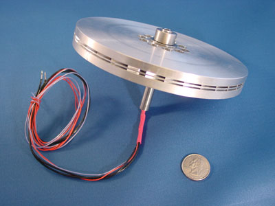
I had an interesting dream last night (don't ask, its just the way it is :wink: ) & it involved an axial flux motor less than 5" in dia. Fully enclosed so as not to fill the motor with ferrite as I drive up & down my dirt road.
(that is a concern regarding an outrunner) EDIT:removed non topic observation

I have no training in electrical theory & even less regarding an axial motor, But I am a "Maker" with the ability to prototype.
If someone can link a few sites to "mine" I will continue the research. I also would like any opinions on feasability of the basic design. I have a drawing of the design started.(Just no way to post it-2-d autocad)
I have a full schedule of projects in progress but I would make room for this if it seems viable.
 
Thud,

I've learnt a lot from doing searches here: http://www.rcgroups.com/electric-motor-design-and-construction-361/

Something from my Bookmarks: http://books.google.com/books?id=jearIV8uVPoC&printsec=frontcover#v=onepage&q=&f=false
 
Thanks Miles, you are a phenominal source here.(I will be stoping at the library tonight)


edit: removed non-topic reply to original thread.

Here's a q&d 3D take off.
testmule2-1.jpg

lunch time take off- to convey concept.(missing lots of detail)

Edit: newer drawing to show stator teeth & set up for LRK winding with oposing coils on the rotor.
some specs:
1/2d x .25t neo disc magnets
14 poles
hall's for comutaion should be effortless on this.
the goal is to match the performance of the outrunner designs & remove the spinning can & the issues involved with that.
These magnets seem to have more pull than the largest outrunner set-ups= more tourque potential? (yes i am aware of the angular interpolations regarding tourque po-blah blah)
I know there must be a long thread about this somewhere on a forum somewhere. I just havn't found it yet.(found several now :D )
hope this sparks some conversation(or at least a flame or 2 :p )
& again- I am electricly retarded.....stricly an applications guy.
what have I missed?
Is this folley?
should I invest $20 & 10 hours to build a test mule?
& thanks in advance
 
Thanks Miles,
I thought my drawing might spark some conversation......I guess I am either out in left feild or the only one contemplating motor design & its application. (I suspect the former) I have been researching motor design heavily the last week & actually orderd a few magnets for experimentation.
Winter is coming & I will need something to do when not shoveling snow. I have a couple books on order from the local library that will let me "do the math" for design purpouses.
 
Man, that is thin. :eek: Thud, I'd say go for it, unless these guys have a patent?

I'm still struggling to understand the axial flow concept ( I searched for a Wiki article, but couldn't find something with a simple explanation...). If I understand your drawing, the windings go on the three pieces sticking out on each end piece and the magnets go on the disc in the middle? Are there really only three stator windings per side, or are you only showing three?

You guys are giving me another headache... :roll: :mrgreen:
 
Gary,
I think 3 are all thats required, I show them on both sides to ballance the pull on the rotor.
Garry:( I searched for a Wiki article, but couldn't find something with a simple explanation...).
I am discovering all kinds of technical info so far over my head.....I am getting a headach!

This is my take on the wheel motors I have seen in the solar powerd racers, applied to a universal mount, high efficency motor. The leverage of a larger rotor & the ability to reach max magnetic potential of the stator (not as space inhibited by the next winding) make me think this may have great tourque potential & low KV.
I may have read something (or it was something I ate) as I dreamed about in detail that night.
As Ive said before, I really have no idea if this has already been done & proven foolhardy. untill someone steps up to steer me straight I will continue experimenting. I also think Hall sensores are going to be included on the prototype.

As far as patents go I am not worried. You can build anything you want for yourself. Selling for profit is where patents & copyrights get sticky.
 
Thud,

check out some axial alternator links. Lot's of activity is happening
on the generation side.

http://tech.groups.yahoo.com/group/axialflux/
 
GGoodrum said:
Man, that is thin. :eek: Thud, I'd say go for it, unless these guys have a patent?

Thud's design is quite different to the Launchpoint one. I posted that because it looked about the right scale for us. It has outer magnet discs which is why they need the Halbach array. The first axial flux motor was built in 1831, so there's plenty of history...
 
If anyone is following this, here is a nice paper.
my research continues.....
http://kron1.eng.ox.ac.uk/media/papers/Woolmer_paper_2007a.pdf
 
Here is another fellow who's interests seem to parralell a lot of the things we are doing on ES.
his blog is a good read:
http://scolton.blogspot.com/
He has a "Nuts & bolts" philosophy on motor design I can apreciate.

It apears my design falls into the segmented stator group of Axial motors.
My variation is in ballancing the stator coils on the magnet rotor in an attempt to reduce axial loading on the rotor. & the overall scale for bicycle/light EV appliction.

I have found some existing examples but I am a bit skeptyical, as all of the papers published seem to favor the design in the title of the paper, plus all &the papers on axial's are only compairing themselves to other Axial designs.
Experiance tells me, if it was a "better design" we would already have them. I feel I must be missing something fundimental as it looks very easy to manufacture & the aplications would be more than bicycles.

I am studying eddy currents & their effect in motors, & the geometricial relationships of stator teeth & phase pulsing (comutating).....Trig/schmigg :? (head ache for sale)is LAR engineering acceptable around here :p

I am also still searching for a document with a direct comparison of a standard wound (out runner)12tooth stator vs an LRK wound stator with = copper weight in both, tested in either delta or wye....natural selection would weed out an inferior design. I can only assume they are too close to in performance to obsolete one or the other. Any questions in the rc groups have yeilded conflicting arguments. stalemate!!!

There are examples of 3 tooth axial motors on you-tube so I know that it is "do-able" The pole counts start at ten & go to "too many to count"

I am hoping an expert in all this theroy can point us in a direction, or point out the pitfalls of the current thought process. Never the less, I have some stuff on order & will be building a test motor to see what it can do.
Any one here have a dyno set up for some compairisons? any thoughts on a simple dyno?

should I post a build log here?
My high school education is getting streached to the limits the last few days. Thats enough for now.
 
Thud said:
Any one here have a dyno set up for some compairisons? any thoughts on a simple dyno?
Yes, time to look again at dyno designs... I was thinking of putting together a Prony brake but I still haven't got around to it...
 
You might check out the Mars brushless motor. Something like a scaled down version of that sounds like what you want. I can't seem to find pics of the insides of one, but I've seen one taken apart. The interesting feature is the stator core, which is made from a really long strip of iron rolled up. The strip has slots in it and somehow they have all the teeth lined up when it gets rolled up.

If there is a stator on both sides, the axial forces can be largely balanced and you don't need iron in the rotor.
 
Hello,
Thud, I read the Scolton information and was quite impressed. This afternoon, I decided to do a Axial Flux Motor in Solidworks that I would really like to see designed. The important features are that the drive shaft can be easily modified for the applications of others. I was at NASA (too many years ago to remember) when NASA was involved in flat copper windings/wiring concepts. This was in the Saturn V days. Scolton's use of flat wiring is very impressive. I have enclosed two JPGs for others to look at and laugh at (if necessary). I would use two slaved microcontrollers (PICs) to do the PWM drive for six stator poles pairs. This would allow PIC 18F types to be used and they would have plenty of speed to do a great job. Scolton's schematic is also very interesting. He alludes to a computational problem to really make things work elegantly. In my concept, the stator windings are all separate and their wires are funneled through the hollow stator shaft to the non drive shaft side. The twelve stators work in pairs. The rotor spacers are not shown, but they keep the rotors accurately spaced and allow simple bearings because side (axial) loading must be minimized. There is probably something glaringly worng with this concept, but, I thought I would throw it out there for comment. Overall dimensions are about 100mm by 100mm.
kenkad
 

Attachments

  • afm assy1.jpg
    afm assy1.jpg
    26.6 KB · Views: 3,226
  • afm assy2.jpg
    afm assy2.jpg
    32.1 KB · Views: 3,198
kenkad,
Welcome to the discusion. I am so happy to know there are people like S.colton & they are putting their experiances & knowledge on the web for near dullards like myself to benifit from. Nice drawings also. I have solidworks, but for sketching I am kind of stuck in AutoCad (old dogs & sutch)
as for his work on the controllers, I confess that is way over my head. I can solder parts & pcs in wherever you tell me, even check em with a meter, but anything beyond a resistor or capacitor & I am in trouble.

I am intreaged by the winding with flat stock. His site is the 1st Ive heard it referanced. Copper foil & kapton tape insulation. I wonder what the effect is in the flux strength. Seems amperage potential would be great.

I did turn a rotor & retainer ring for my desin mule this morning. I will cast the magnets into it with a poyester resin. I plan on using soft iron for cores on the stator teeth. Many individual wires glued together to form a sudo laminated core. Reading the Oxford paper, having the stator in segments reduced eddy current potentials. whether that is an issue at this scale is prolly arguable. I am still waiting for an expert to show up & point out the "obviouse" flaw that any 8 yearold would know :oops: . keep thinking about it & lets have some debate on design criteria. See if we can't stir up some interest. Thanks,Todd
 
I'm not sure what effect having air space between the wires will be. I suspect it will just behave like a smaller core. Flat laminations are 100% fill. You need to make sure the core laminations (or wires) are insulated from each other. Only the part of the core inside the windings really needs to be laminated. The back iron (if used) can be solid.

Using flat copper spiral windings, you could possibly make a nice coreless motor. Heat dissipation for the windings could be an issue, though.
 
Howdy,

Thanks for opening this thread and all the informative resource materials... I've finished combing through them (been reading them all weekend) and I see why these motors aren't in mass production..

I'm not even talking about the 12K USD for a "motor kit" with nominal 1800w rating and thermal design to handle twice that for peaks.. so 3600w... the efficiency (in the aurora) is sweet @ 97.5% so I suppose if your only concern were efficiency (ie: solar only car) and you were doing competitions or true R&D then sure it might be worth that price but when you consider a traditional 400.00 bldc motor such as the astro which can hit near 93% efficiency (I think this was the spec) and with sufficient gearing be overloaded - Recumpence would sell you a dual stage reduction unit with mounts for about 450.00 all included so 850.00 and were at about 3kg-4kg or 1/2 the weight and matt runs these beyond 3kw frequently?

True this would be very efficient but it will require a 6 phase controller capable of driving it (which could also be nice as it would/could open the delta/wye as an option of the controller) and it does fall within the RPM range where delta/wye would be useful as it is in industrial applications to avoid large current draw on starting torque. I doubt the commutation of this motor is simple to execute, though yes a pair of PIC or even atmega avr would suffice (I think @ 16mhz the theoretical electrical RPM limit would work out to be about 4100 K RPM - should be sufficient for a basic design/test).

The reason we don't see them is the degree of precision with which they must be manufactured - the tolerances on these are extremely tight and the design would require very tight tolerances no matter how we changed it (if we wanted to realize similar performance)... I think that a normal, well engineered and built BLDC 3 phase/6 phase may be the same level of efficiency when operated in it's "sweet range" and they are obviously more resistant to manufacture variances.

Just my .02
Mike
 
I got a quote from an axial motor designer last week, and the prices were actually pretty close to costs for a US manufactured inrunner of similar weight and power. An 8" motor would be just right for our EV use, it would only need 1 stage of reduction with the right pole and "slot" count.


I also sent out an email to one of my RC motor manufacturers to see if they would be interested in manufacturing the design. They have the precision and accuracy to pull it off, as well as great costs for labor and materials. No major tooling would be needed. Flat plate, wire, and magnets are really all that is needed for the design.
 
John,

I stand corrected... if these can be produced at a reasonable cost and offer similar efficiency to the above posted reference system and only require a single reduction stage then yep - might be worth it!

Can't wait to see what comes of this - I had assumed outlandish costs for the level of precision required for assembly, this is why I'm usually happy to be wrong = )_

-Mike
 
It was off the cuff quote from a rep, we are working on official paperwork right now. I was pleasantly surprised that my estimates were not far off.

Basically looking at the average Joe having them available at $400 per. Roughly in line with Astro.


It seems that the assembly isn't that bad really. The biggest part would be flexing of the magnet mount face. If there were dual magnet faces opposing each other, they could be connected to remedy this.
 
Back
Top