Battery bms repair

XxHaimBondxX

10 mW
Joined
Apr 8, 2023
Messages
23
Location
Albany, NY
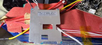
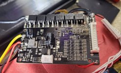
Got a bike with defective battery, not charging, but puts out about 15 volts. Inside bms looks like transistor #4 cracked. #6 doesn't look very well either. Other than soldering connections, the base seems to be solidly glued. Easy to replace?

Perhaps replacing entire bms, can anyone recommend a replacement?


20230408_194830.jpg
20230408_194837.jpg
 
I may have completely messed up ordering a wrong bms and charger. When they list "14s", does that mean 14 white wires, black and red, in the connector? Mine has 13 white wires, red and black, total of 15, so is that 13s?

Cells are Samsung 18650 26j.

Also I'm not able to measure any voltage, the battery has completely 0. Never seen one discharge this low.
 
Last edited:
When they list "14s", does that mean 14 white wires, black and red, in the connector? Mine has 13 white wires, red and black, total of 15, so is that 13s?

14s means 14 cells or cell groups in series.

The number of BMS balance / sense wires can vary depending on BMS design, as previously noted. If you don't know how yours is wired, the safe bet is to measure the actual cell (or group) voltages as previously noted to see how many total groups you have.


Also I'm not able to measure any voltage, the battery has completely 0. Never seen one discharge this low.
If the voltage at the cells is actually that low, they are unsafe to recharge. They could be damaged in a way that could lead to fire at any time during or after recharge, whether they are being charged, discharged, or just sitting there.

This is one of the cases the BMS is there for, to turn the charge port off and prevent recharge of the damaged cells.


If the 0V is only at the BMS charge / discharge port, but you have correct expected voltage at the actual cell block main + and -, then you just need to measure the individual cells (or parallelled cell groups), to be sure none of them individually is below safe recharge limit (2.8v is usually what is listed on the spec sheets, but you can look that up for your specific cells).
 
If the 0V is only at the BMS charge / discharge port, but you have correct expected voltage at the actual cell block main + and -, then you just need to measure the individual cells (or parallelled cell groups), to be sure none of them individually is below safe recharge limit (2.8v is usually what is listed on the spec sheets, but you can look that up for your specific cells).
Yeah I tried measuring everywhere, I even unsoldered bms to make sure it wasn't messing things up and still can't get a reading at main power wires, maximum it shows 1 volt. I found a local battery seller that will let me try it on the bike.
 
It sounds like you've done this, but just to be certain, since I sometimes am not well-understood:

By "main power wires", do you mean the ones on the cell block itself? Like where the blue arrows in the borrowed image below point to? (this is where the red and black meter leads need to go to, with the red lead on the Volts plug of the meter, and the black lead on Common or Ground, with the meter set to DCVolts and either Autoranging or 200V).

I would test at the cells, not the wires, in case there is a safety device (fuse, etc) within the wiring.
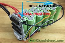
completely-wired-pack.jpg

Also, does the meter read a voltage when testing something else, like a 9v battery? (just to make sure the meter itself works and is correctly set to DC Volts.)


If the meter is verified to work, and you get 0V at the main cell block + and -, you should verify the at the cell groups themselves. If it's spotwelded cylindrical cells like the image I attached, then you can put the black meter lead on the main negative end, and the red lead on the other end of the same cell group. Repeat this for each cell group in the pack, moving both leads each time, and it will tell you what each group voltage is. If the groups all read a "normal" voltage, somewhere between 2.8 and 4.2v, then the cells themselves are fine, and there is either an interconnect issue, or a fuse or other safety device that has disconnected something in the series connections.
 
Also, does the meter read a voltage when testing something else, like a 9v battery? (just to make sure the meter itself works and is correctly set to DC Volts.)
Actually I did try it on a 9v battery, which read 7.8 volts because it was pretty old. Meter is set to DC 200. There are no fuses in wires, I tested thick RED and BLACK wires, also at the battery cells as well. I will unwrap this battery tonight and attempt testing groups. Thanks for all your help.
 
Ok. It sounds like either something completely shorted out the battery and was connected to it long enough to kill the cells, or there is a fuse somewhere in the series connections that has blown from an overload.

If it's the former, the pack is literal trash, and should be recycled. :(

But if it's the latter (and none of the cells are overdischarged) you can fix that, replace the BMS, and keep using the pack for whatever life it has left. :)
I couldn't get any decent voltage reading anywhere, but I did buy a new battery. However, when wired I'm getting error 30, then computer shuts off, regardless if everything is connected or not. Seems like end of the road for this set up.
 
Error 30 in some setups is communications error, which usually means a poor connection or wiring fault between controller and display, or one or other is damaged.

If the controller can be turned on and operated without the display (headless) by manually connecting it's battery+ output wire on the display connector to it's keyswitch/ignition wire, and it doesn't shutdown, then the display may be the problem.

Depending on the system and connector type used, the pinouts for it may already be available to see which pin is which, to do that test.

If the system works this way, and you don't need anything ohter than the default powerup assist level, etc., you can just use the system as-is.

If you need the options the display provided, then if you can get an identical display (since displays are generally not inter-compatible between different controllers, and vice-versa) you could test this, but it may be more cost-effective to just get a new controller/display combo that does the job you want this system to do for you. (if you get one that uses the same display, then you can also swap parts to test things if needed in the future should a problem arise with the new system).
 
Back
Top