battery medic mod :P fast discharge

Please post pictures if you can.

-methods
 
Both my boards are red but read very different voltages between the same pack and get even worse once I start balancing. Just wish I could use methods bms board with a cell pro. Be perfect. And use the cell pro for lvc to throttle.

I'll post close up pics of what I have tonight.
 
Define big difference?

20mV?

So one reads 3.87 and the other reads 3.85?

-methods
 
6s Battery

CellLog 8s reads:
1:4.093
2:4.093
3:4.089
4:4.093
5:4.092
6:4.095

#1 Ebay Balancer (modified with 3.9ohm resistor)
1:4.09
2:4.09
3:4.09
4:4.10
5:4.09
6:4.10
**while recording a few cells change +- .01v

#2 Ebay Balancer (unmodified)
1:4.07
2:4.13
3:4.09
4:4.10
5:4.10
6:4.09
**doesn't vary voltage while recording

With the modified balancer it jumps all over the place while operating unless it's hooked to my bike battery which is a ~12Ah. Also described earlier in the posts it cuts on and off roughly every quarter second as can be viewed on the celllog. When I just leave it to do its thing it gets the battery roughly to within ~20mV.
 
IMG_0350.jpg


IMG_0349-1.jpg
 
Thanks for posting those numbers.
I look forward to taking some data of my own from the "good" ones and the "bad" ones.

I don't mean to look a gift horse in the mouth - :) - but is there any chance you have a Fluke meter or other high quality measurement device to get the baseline with?

It would be interesting to know what the actual values are so that we can calculate the true max and average delta of each channel.
I would like to understand both the accuracy and the precision.

If it is precise but inaccurate we can solve that by trimming the divider resistors. (for instance if one channel is worse than the others)
If it is inaccurate and imprecise then I would like to know how imprecise.

I don't mind inaccurate - that we can compensate for so long as it is precise.

oh boy - oh boy - oh boy

Hey - I thought Fechter and Goodrum were working with these like a year ago... Am I blazing old trails here? Suppose I should UTFST

-methods
 
Yeah, Gary came up with this a couple of years back. He was going to produce some, but for some reason let it drop..
In my experience they work fine...as long as you don't leave them connected too long!
 
No Fluke meter sadly. Just a simple ol craftsman multimeter. I figured the Celllog was everyone's favorite choice for accurate measurements since they calibrate em before hand. Would you like I unplug and plug back in the celllog and battery medic, lets say 5 times each to check for precision and use multimeter to check for voltages thru the balance leads then check on battery leads? That sound like useable data for you?
 
If you feel up to it - go ahead and run a test - but don't worry if you are busy. My units should be here in a week and I will take some data as well.

I ordered 29 high quality units and 1 low quality unit. I know... the one is not enough to make a proper comparison - but basically I wanted the one to take pictures for people who are trying to compare the versions.

As far as leaving them in too long... It is pretty clear that they are heat soaking. There could be a cheap/easy mechanical cooling solution to that. Or is it the power they draw that causes problems over a long period of time?

Oh well - either way my mind is made up.
These will work as a stop-gap for those who are bulk charging without an onboard BMS.

-methods
 
I just attached a excel sheet with the numbers I got. The celllog had different numbers when measured 5 different times. The multimeter and balancer readings never changed over the 5 measurements so they only were written once to keep it clean. It was very surprising the celllog readings. I always thought of the celllog as a very precise unit that most everyone on ES loved. It was purchased from HobbyKing during the short time they were not on backorder so I assume it is the real deal. Well Methods let me know if that helps at all. I'm just going thru college so it seems I have some free time to play around with this. Also the celllog can have each channel manually adjusted to read better but with how unprecise it is, it would be hard to calibrate properly I think.

Cheers
 

Attachments

  • BatteryTesters.xls
    16.5 KB · Views: 110
Amazing how two tests can create such different results eh?
Or at least our impression of the results.

I have owned and played with most of the meters on the market. I had the first cell log before they had logging - what I remember about it was that it was a very sexy mechanical package. The feel of the plastic was like microfiber. It is a nice looking product - this is why people like it I suspect.

But... people do not test the precision. Some test the accuracy, but few the precision.

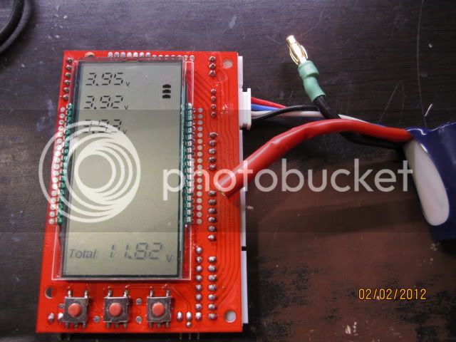
Looking at the cell log data the swing is not really that bad.
about 5mV on each channel right?
That is actually pretty good...

I suspect that the other meters are probably rounding or averaging results and that is why they stay still.
My guess is that they will make a larger jump once a threshold is stepped over.

Good job with that data. Now it is clear why I asked to see measurements from a calibrated DMM :wink:
Next test you might want to do would be to take your DMM into the lab at school and calibrate it against a known good DMM.
I did this at work as follows:

Grab two calibrated DMM's
Set up a spreadsheet

0.001V
0.01V
0.1V
1V
10V
100V
1000V

Take all those measurements with your DMM and the two calibrated DMM's
My guess is that you will find that your DMM is off by up to 1% and that value goes UP with voltage - so at 100V you may read 99V or 101V. Seems like no big deal until you are trying to measure a 24S pack that you want exactly at 100.8V. That type of measurement requires 0.1% accuracy to take. The scary thing is that your DMM will say 100.8V when it could be 101.8V or 99.8V. They display a higher degree of accuracy then they can measure which is misleading. They should just truncate that data to 100V or 99V.

I also found that my meter would have "resolution steps" as it moved through the auto-scale sections.
In the end I just memorized the offsets and mentally added them. For instance, when i was reading about 100V I knew that my meter would read about 1V low so I would add that in.

btw: This was like a Radio Shack DMM - maybe $30

Then do the same with current

1uA
10uA
100uA
1mA
10mA
100mA
1A
10A

My guess is that all of these readings will be right on.


Then.... once you graduate and get an awesome job watch Ebay and grab up a nice Fluke DMM. :D
My experience has been that if some dumb-ass blows the internal fuse they will sell it for cheap - not understanding that it is just a fuse.
Maybe $150 for a nice DMM with all the fancy features.

worth every penny.

-methods
 
These balancers suffer terribly from heat soak. Even the stock one I used almost broke as I just left it on and it started reading 7.xx V. The modified one I got the screen to get black spots even though the large resistors are spaced away from the board. Just be sure u got a fan on them when u begin testing and modifying.


cheers

Speak of the devil there is a fluke for sale on craigslist $100.
 
We will test these Battery Medics and modify them however is needed to make them more reliable.
Could be as simple as modifying the plastic housing for better airflow.
Maybe a clever heatsink...
Maybe removing the internal shunts like the OP did and just pushing the resistors (axial) away from the PCB will be enough.

-methods
 
just quick update there still going strong :p also noticed in cold thay read off then at room temp also thay make amazing hand warmers :p guess i found a use for thoes old turnagy cells that where a few mah low for the pack i salvaged lol
 
Well I separated the 2 boards apart. Perhaps instead of building a external board with larger resistors I can just move the whole resistor board. I'll try and get it wired up tonight and see if heat is a issue with the main board. I'd like to post pictures of what's on the board but my camera just won't focus well enough. :roll:
 
Hand warmer?

hmm... 5W actually makes quite a bit of heat
6S 5Ah pack = 111Wh
111Wh / 5W = 22.2h of use

So if you take a Hobby City 6S pack and hook it up to a 5W hand warmer you will be good for 22 hours. Man - never thought of that!
(note - may want to use a regulator to keep the temp from swinging with voltage)

-methods
 
methods said:
So if you take a Hobby City 6S pack and hook it up to a 5W hand warmer you will be good for 22 hours. -methods

Or 40 seconds if you short it with some pocket change :twisted:
 
does anyone know how to 'tune' the bm's? ive done the usual mod for quicker balancing but ive noticed there's about 20-30mV difference between different units. They're pretty consistent within themselves, just from one medic to the next there's some variance I'd like to reduce/eliminate if possible. A bit anal I know, worrying about <30mv but if it can be done without too much effort...
 
Sorry to ask a stupid question if this has been clearly explained somewhere on this thread, but I am a little slow on the uptake. I can see on p1 that the instructions are to "remove the smt" transistor (i don't even know what that is), and then I can see where the new resistors have been soldered into the board (although has someone confirmed what are the best value resistors to use? People seemed to be talking about different value resistors). But as I said, I don't even know what an SMT transistor is, and although I understand concept of what is being done, I don't have the vaguest understanding of the board and what it is doing. Has someone done a step by step instruction of this mod for morons like me? Or can someone put in clear steps with limited syllables what it is I need to do for the mod?
 
I'm on the same boat but I just grabbed one of my balancers and tried the mod. The smt (surface mount transistor) as far as I can tell are the small resistors that line the top of the board. He removed all the small resistors and replaced them with one large resistor with a lower resistance than all those small smt ones in parallel equaled. This makes the balancer capable of discharging almost 1000mAh instead of 200-300mAh. (guessing) Helps for larger batteries so you don't have to wait so long.

I just removed all my smts and just installed the large resistors but I put a lot more space between the board. Removing the smts helps eliminate most the heat soak issue I was having while leaving it on to balance for a hour or so and can be left without any active cooling.

Hope that in some way helps you out. I'm doing my best to keep up with the brilliance of the guys on this board. Haha, makes me seem like the slow kid reading these guys talk shop.
 
Thanks FastDemise, I am really keen to get this mod working as I would love to be able to speed balance my 20S 20ah and 12S 40AH pack in conjunction with bulk charging, but the battery medics are waaay too slow currently, so this would be awesome. I am just worried how many battery medics I will frock up before I get it working. I have a few to spare so I guess I should just at least try with one and see how I go. As I said, I can see where the solders are being made, I just was hoping someone had done a guide for idiots like me, and confirmed the value of the best resistors to use.

Cheers, Phil.
 
Well Phil I have messed with my board multiple times and it still works great. Since is is two seperate boards the heat from soldering doesn't effect the rest of the medic. Removing the smts was a pain. Just heating up one side with the solder iron then quickly touch the other side. Then just repeat a couple billion times and you are done.

Check out Methods thread. He just got a big shipment of these medics and is modifying them.

Lance
 
Sorry for being so dumb on this, but if the OP or Fastdemise, or anyone who has done this mod, am I understanding this correctly. In the photo below, I remove the little black things in the red box, and then I solder a 6.2 ohm 5W resistor from the top yellow square to the bottom yellow square (and I do that for each line).

Is that correct?

Batmedic.JPG
 
Back
Top