Battery newbie in over his head.

fill

1 kW
Joined
Aug 17, 2023
Messages
475
Location
uk
A chain of repairs led me to changing the connection blocks on my backup bike hailong battery and sled as when upside down for the fix/testing the battery 'fell' out of connection with its spade and clip connectors due in part to snapped retaining slides on the battery base.. SO a change to the Pin and socket style which is used on my other bikes would then also allow more battery sharing and should resolve the connection issue too, win/win

When done I lamented the lack of an on/off switch on this battery in the local forum where the original issue/fix was under discussion, and the possibility of adding a switch was raised by either using a switch connected to relevant solder pad if present on the bms pcb, or if not by interrupting one of the sense wires instead.

Sounded good to me and amazon could supply some small waterproof latching switches quickly, so i got stuck in and revealed a bms pcb with 2 solder pads next to a 'SW' label.. unfortunately attaching neither a momentary or latching switch to these pads had any effect on the battery output voltage.

So i opted to snip the sense wire labelled B2 connecting to the bms through a 11 wire/connection plug/socket labelled B-, B1,B2,B3,,B10, B- being a black wire B10 a red wire and B1-9 all yellow wires. I selectd B2 as it appeared to have the most wire slack and would be the easiest to hack a switch into.

well that didnt work either, I have a led volt meter attached to the battery output, and pulling the whole 11pin plug from the bms cuts the battery output voltage straight off. so I dont think its residual capacitor charge? and i left the battery sat with wire 2 for for over 30 mins and the lit voltage display showing 1 decimal point didnt drop at all.


Testing the sw solderpads with a latching switch it depresses to make contact and is slightly raised (1-2mm?) when contact is broken.
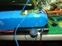
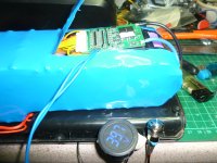
battery switch1.JPG

battery switch2.JPG


After 15minutes minimum of cutting the B2 wire
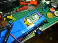
battery cut1.JPG

opening the battery wrap to confirm the B2 wire was connected to the second set of cells in the pack..
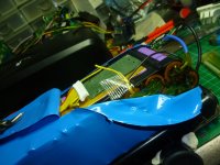
battery cut2.JPG


Next thing is of course to repair the snipped wire, but after that, should i cut my losses and wrap it up and live with a switchless battery?

OR should i continue with the wire snipping roulette game??

Or is some guru gonna tell me my bms is a worthless piece of ****???


BTW the original fix is a hall sensor error (KT display er-03) and probing the sensors while spinning the rear wheel while the motor system is powered up for the 5v logic system is what i want to get on to ;)

If you got this far thanks for reading..
 
There are some transistor shaped solder pads missing components near the switch input, so I'd say the switch capability is missing from this BMS.

I'm never going to recommend cutting a safety monitoring feature to disable the output.
 
The reasons behind the wish for a switch to isolate the battery output are simply a desire to stop the loud cracks pops and bangs that occur most of the times i plug in a live battery, due i have been told to 'hungry capacitors in the controller' And to also stop the associated damage and scarring of the battery and sled terminals too.

That and the simple reach down and flip of a physical switch is way easier than looking at and fumbling a handlebar display with a number of presses just to cut the power completely...

Here where batteries are bolt on and vulnerable AND represent a good 40-50% of the value of the bike they do not get left on the bike in public.. so i would prefer not to treat my batteries to 3-4x violent discharges daily if i can avoid it..
 
Hey if the consensus of the wise and knowledgeable is patch it up and cut your losses, so be it, I am out of my depth with a slither of an appreciation of the circuits involved (as black boxes) and no electrical engineering know how- i can do plug n play arduino and add an odd resistor to pull logic one way or the other but?????????

At least now the bike is fitted with the same battery connectors as the others so switchless battery can be relegated to last choice.. or i could buy a new bms.......


?? since ive confessed my level of competence... Could a hint of a significant draw be whats required to tip the protection and cut the battery out put,?

The only test i can think of however is to slide the battery that appears live with a sense wire cut onto a bike and if it fails to bang/pop and subsequent readings of the terminals are 0v?? would that be sufficient ratification???

Then if re-connecting the cut connection restores the full output, have i a workable solution? I would have to remember to ensure the battery is turned on Every time its charged, but as the switch (if fitted) will live next to the charge port that and a sticky label shopuld be reminder enough..
However i am unaware of the full consequences should i in error charge the battery to 42v with 1 x sense wire severed.?? if it would even work??
 
There's plenty of threads with examples of switches that work for the full battery current and voltage without arcing and potentially welding the switch closed. Rotary marine battery selectors, circuit breakers, etc.. If you really need a battery switch, and your BMS doesn't have pads for an on/off switch, you should be using one of those.

It's also ok to put a smaller switch on any ignition/key switch pins the controller exposes since, although that runs at full battery voltage, it's only enough current to run the low voltage converter in the controller that powers the logic circuits from the battery voltage, not drive the bike.

It sounds like you don't even need one anyway, though. There's plenty of connectors with anti-spark resistors built in for just a couple dollars. Commonly QS8 or XT90. E.g.:

These are not mechanically complex devices. You insert the plug partway, the capacitors start charging via the connection with a resistor inline, then insert the rest of the way and add a connection without any resistance.

Regarding the BMS, I would repair and replace everything you touched regarding it and leave it alone. The wires going to each p-group are for voltage sensing the different parts of the battery and ensuring the battery is balanced. If you mess with one, and you shouldn't, you should do the same to all of them to prevent the voltage measurements from not being comparable while the BMS is trying to protect you from burning down your house.
 
Thanks for the input @TDA78 , @Diggs , and @lnanek (thought your handle started with a capital i for a while..)

Fwiw batteries generally live and get charged in the steel garage separate from the house.. Though I also wish to remain garage fire free too...

I have browsed over lots of switching options and many of the above suggestions could work for some bikes, such as anti-spark xt60/90 connectors between the battery sled and controller that could be pulled prior to adding a battery-.. But for the bike with the controller embedded within the battery sled hard soldered to the battery terminals.

Ironically all the easy solutions that work on 2 bikes leave my daily ride 'out of the spare battery loop' altogether.

And solutions involving too much bolt on extra are nonstarters from the get go.

Oh well worth a look into..
 
I've also tried switching off a balance lead, and it did nothing, It might have to be an important one like the the last B0 lead. Will check that next time I connect up a BMS.

I've bought a BMS and forgot to order the switch option, Bought a second one with it. Both appeared identical as both had sw pads for a switch, but the non-switched unit didn't react to a switch, I concluded that they must have installed the option via programming, after tracing the leads to the microcontroller on both boards and seeing no zero ohm resistors ti bridge the contacts as you might expect.

I use XT60's, and don't believe they come with anti-spark. I find the XT90's too large. I don't mind the XT60's popping.
 
Elsewhere others have pointed out the -ve soldered connections connecting to the BMS are not where they are expected to be,
and both charge wires are connected at the output terminals.. and other peculiarities with this bms ? mosfets in serial connection?

However my original target was met, This battery and bike is now using a terminal connector that will maintain contact on a bumpy ride and even when upside down with minimal retaining clips surviving on the battery. so i can now test the dodgy motor hall sensors.. with any battery in my collection ;) And all my batteries and bikes all share the same connection terminals boosting the theoretical range of all bikes (when running)

btw other than a beat up case thats been kicked off the bike more than once by the looks of it which is also why gravity wins when its upside-down for a FREE 2nd use battery it charges upto 41.something volts, holds a fairly good charge in comparison to a similar sized battery bought new last summer, and i have had no other complaints beyond jumping out of my skin when its connecting and popping catching me off guard.. so even with its peculiar? bms it still does what its expected to do.. and the mantra 'if it aint broke.......' is echoing through my mind atm.

however if i had just spent 30 minutes digging out a 10k ? resistor for the hall sensor testing circuit (from grinn iirc) using a 5v power bank psu. I wouldnt have cared about the bike battery falling out of connection when upside down,

But using the bike battery is EASIER!! 1x 10k resistor easier to be precise..
 
Wouldn't opening the bms' positive supply wire turn off the bms?

Probably in any other case, but yeah i snipped B10 or the red wire after repairing the cut in B2 so it appears it can also draw from at least 1 other +ve connection too?? still got to fix that..
 
Some skate boarders just throw an extra XT90 port on their system that interrupts battery negative or positive to the controller. Then they plug in a XT90 anti-spark with shorted ends as a key to connect up that interrupted wire between battery and controller.

Could probably shrink the whole system down to XT60 by just having a hardwired, always connected high resistance connection that's plugged in anytime the battery is in, e.g. just a big resistor inline so it can charge caps. Then plug in your shorted XT60 key to connect the low resistance path. Pretty easy to fit an extra XT60 port for the key somewhere you can drill some holes.

The traditional solution is nice because the anti -spark resistors can die, though, and it's easy to make a new key.
 
Back
Top