Hello everyone!
I am attempting to bench test some brand new SF41F hall effect sensors I got from aliexpress using Tommycat's thread as a guide.
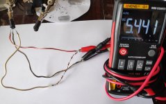
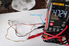
I followed the diagram and wired up one of the sensors to a 5V wall adapter, which provides stable 5.44V. The sensors supply and ground are directly connected to the power supply. Here I am measuring the power supply's voltage

I combined a bunch of resistors in series to create a 10Kohm resistor as per the guide.

I then connected the sensors signal wire to the 5V supply through the 10Kohm resistor and connected the multimeter leads to the power supply ground and hall sensors signal line respectively.

All of the connections were soldered as to avoid any bad contacts and I tested 5 different sensors, but for all of them I saw no voltage change when putting a magnet (one from a 1000w motor) right next to the sensor in all kinds of different orientations.
I feel like I am making some mistake in the testing methodology or something else is wrong because I doubt that all of the sensors could be defective.
Any help or suggestion would be appreciated, thanks in advance.
I am attempting to bench test some brand new SF41F hall effect sensors I got from aliexpress using Tommycat's thread as a guide.
I followed the diagram and wired up one of the sensors to a 5V wall adapter, which provides stable 5.44V. The sensors supply and ground are directly connected to the power supply. Here I am measuring the power supply's voltage

I combined a bunch of resistors in series to create a 10Kohm resistor as per the guide.

I then connected the sensors signal wire to the 5V supply through the 10Kohm resistor and connected the multimeter leads to the power supply ground and hall sensors signal line respectively.

All of the connections were soldered as to avoid any bad contacts and I tested 5 different sensors, but for all of them I saw no voltage change when putting a magnet (one from a 1000w motor) right next to the sensor in all kinds of different orientations.
I feel like I am making some mistake in the testing methodology or something else is wrong because I doubt that all of the sensors could be defective.
Any help or suggestion would be appreciated, thanks in advance.


