Hub motor troubles -- possibly Hall Sensor -- not sure how to properly test

bjorken

1 µW
Joined
Apr 9, 2025
Messages
3
Location
San Francisco
A while back, I experienced an axle spinout followed by my motor refusing to function and throwing an "Error 24" on the HUD. After many google and youtube searches, I was able to disassemble the hub motor but I'm now stumped on what to do next. Based on the error I assumed that either one or more of the hall sensors needed replacing, or perhaps the whole motor cable had gotten twisted (despite visual evidence of this) and would need to get swapped. So far so good.

The issue I am having now is that I can't figure out how to test the Hall sensors given the configuration of my motor and cable. I.e. the cable comes out of the motor as pictured below, and terminates in a male 3-pin connector. That connection leads directly into the hub controller, so there's no opportunity to isolate individual hall sensor or phase wires for testing with multimeter. The second picture below shows all the wires coming OUT of the controller box, and these don't seem to be continuous with the solder points on the hub PCB itself (but I'm not sure if they should be) since they aren't directly connected to the wire coming into the controller.

I also have one of those cheap ebikle testers, in case that helps. I just can't figure out how to hook it up given the above, same as multimeter.

My questions are:
1) Would anyone suggest a different approach? Am I barking up the wrong tree?
2) Assuming no, is the best next step to crack open the controller box and locate where the incoming cable's wires terminate on the PCB there and test for continuity with hub PCB?

Any help would be much appreciated!
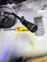


2025-03-28 18.10.13.jpgView attachment 2025-03-28 18.35.22.jpg
 
Is the 3 pin connector the only one coming out of the motor? If so, it would appear the motor doesn’t have hall sensors.
You can use a multimeter to measure resistance between the pins coming from the motor. It should measure essentially zero ohms between any two pins.
 
With the motor connected to the controller, is there resistance when you try to turn the hub? If so, disconnect the controller and try turning the hub again. If there is only resistance to turning when connected to the controller, then there may be a short in the controller. If there's resistance in both cases, then you may have a phase wire short in the cable or motor, which can be tested with an ohm meter as fechter mentioned.
 
@fechter: The three-pin connector is the only cable coming out of the motor, but it consists of several smaller cables that get bundled into one big cable and terminates in the 3-pin. The only way to access the inner cables would be cut the whole big cable, or open up the controller as I mentioned in original post. I'm pretty sure there are hall sensors -- I see them.

@E-HP: I'm assuming you mean ohms when you say resistance. Where do I place the multimeter probes to test this though?

Sorry, I'm a bit of a noob here.
 
@fechter: The three-pin connector is the only cable coming out of the motor, but it consists of several smaller cables that get bundled into one big cable and terminates in the 3-pin. The only way to access the inner cables would be cut the whole big cable, or open up the controller as I mentioned in original post. I'm pretty sure there are hall sensors -- I see them..
We'll take your word that there are smaller pins in the motor connector for hall sensors. You did say there were only the three big pins,

Yes, you have a connection problem.
L1121.jpg

But if there are smaller pins in the controller side of the motor connector, then there will be socket holes for them in the motor side. You could connect your motor tester to those pins.

I believe you have a Julet 1121 connector,

Trouble is .... which pins? You said you saw the Hall connectors in the motor. Well, you can trace them back to the sockets in the connector. Publish that here and you will have done the ebiking world a great service.

Or buy this adapter. it changes the motor to an L1019 female, and I bekieve you can look up the pins for the L1019. Or you cab cut the cable open, and hopefullym they used the standard red and black for Hall Power, and yellow, blue, green for Halls',


Last edited:
Wow thanks @docw009! I looked more closely at the "3 pin" connector and... there are actually 9 pins. #facepalm.

Also, I've now identified the connector as: L915A

Thanks to all the super helpful comments!!

IMG_0170.png
 
Last edited:
I have the L1019 IIRC on my GMAC and Phaserunner so when I needed to test I bought an extension and cut it in half (because I wanted to use it for connecting to other non-L1019 stuff for both motor and controller anyway), then I spliced it back together with staggered connectoins (so none of the connections' uninsulated areas is next to any other, so they can't short out when it's in a straight line). Then I can access every wire in the cable wiht a meter, oscilloscope, or whatever. If I need to measure current I can disconnect any wire's connection to put a meter in series with it. (but haven't had to do that).
 
I'm assuming you mean ohms when you say resistance. Where do I place the multimeter probes to test this though?
What was meant was: Is hte motor harder to turn with the controller connected?

If it is a geared hubmotor, you'll have to turn it backwards to find out.
 
A while back, I experienced an axle spinout followed by my motor refusing to function and throwing an "Error 24" on the HUD. After many google and youtube searches, I was able to disassemble the hub motor but I'm now stumped on what to do next. Based on the error I assumed that either one or more of the hall sensors needed replacing, or perhaps the whole motor cable had gotten twisted (despite visual evidence of this) and would need to get swapped.

Much of the time, an axle spinout damages wiring in the cable, allowing conductors from phases, halls, etc to short together. This often destroys the motor's hall sensors and speed sensors and sometiems thermal sensors, and FETs in the controller, and sometiems other parts in the system.

You'd need to replace or repair the mtoro cable first. The simplest way is to pull the mtoro cable;s damaged area thru the axle into the motor from inside the motor. When there is only undamged cable now in the axle and outside the motor, youc an cut away the damaged cable section and resplice all the wires, making sure you connect each wire only to the wire it was part of.


Once the motor cable is repaired, and motor reassembled, you can try just reconnecting the system up and seeing if ti works. If so, you're all set.

It's unlikely, though, so when it doesn't work youc an then do further testing. However, unless you *have* to use that specific controller, it is going to be faster, cheaper, and much easier to replace the controller with a new one than to start testing and replacing individual parts inside a damaged one, since it may not just be FETs--it can be the gate drivers or even the MCU itself damaged by the shorted wires.

If it's just mtoor halls then they're relatively easy to replace, using in most cases a honeywell / allegromicro SS41 or SS411 hall sensor. There are many clones out there, most of which would probably work fine; almost all these motors use open-collector bipolar latching hall sensors that run on a voltage range of as low as 3.something volts on up to 20-30 volts. If it requires 5v minimum it may not work because many controllers have a protection diode on the 5v line that drops it to less than 4.5v. Mouser, Digikey, Farnell, etc should have good genuine parts if you do'nt mind the extra cost to be certain.


There are many motor and controller testing threads from exactly the same kind of problem you started with aroudn here with various details on the testing processes if you want to poke around for them. ;)
 
Back
Top