Big spark when connecting battery to bike

Hi guys,
i found a very new Antispark connector and was able to do some tests to find out how well they can handle higher volts and big controller capacitance.
They are called XT90S and are compatible with normal XT90. As the name says they can handle 90A continuous and 120A peak.
test methods:

- very low ESR Rubycon ZLJ capacitor bank of 3840µF (multimeter showed 3966)
- 30 Ohm resistor for discharing the caps
- XT90s with 5,6 Ohm precharge resistor (not sure if there are other values available)
- 24s LiPo (exactly 100V :))
- 14s Lipo (58V)
- Jeti 4mm Antispark for comparison (they have instead of a normal resistor a NTC type with 52 Ohm at ambient temperature -> this is better, but later more words)

the mulitmeter was conected to the caps during the tests so i was able to see if they are fully charged or fully discharged and how fast this is going.

R0tmol.jpg


UHl2fy.jpg


qyUQ1o.jpg


24s 100V test:

108RmQ.jpg


the caps were charged in less than a second, but after 20 cycles the resistor was dead. I always could see it glowing through the green part of the connector when putting them together (also the first time and not only after 20 cycles).
in summary 100V and almost 4000µF is a to high load for this small resistor.

this is how it looks inside. it seems to be a similar type of resistor like in the Amass AS150 bullets which also did not hold :(

YjqvqA.jpg


14s 58V test:

MlBY84.jpg


precharge time was far less than a second (multimeter was not that fast). I did about 30 cycles and could not see any sparks - even if i phused them together very quick.
the antispark part became a bit warm but not much.

The Jeti 4mm needed much more time for a full precharge (about 2-3sec at 100V), but they have about 10 times higher resistance. Though the most important thing is they will not blow. If you want to use them for high volts and capacitance make sure you stay for a while at the precharge ring before plug them completely together. The Jeti 5,5mm have 36 Ohm and the 8mm 30 Ohm, so they will charge faster and maybe there is no need to stay on the ring when using them.
What i very like about the Jeti is they have a NTC and no normal resisitor.
this means the hotter they get the lower the resistance will be and this makes sense for precharging. I guess if the XT90s would also have a NTC (probably 10-20 Ohm) instead of this small 5,6 Ohm resitsor, they would hold more volts and / or more capacitance.

finally a pic how the connector system comes. on bottom there is the 3-pin XT60 type connector which is perfect for phase wires.

SK1cxs.jpg
 
What is the general consensus of the best way to have a precharge resistor?

Just make one of your own or buy a connector?

What I am thinking is the best way is to have a small wire come out of the back of the positive battery connectors and solder in a precharge resistor with a connector.
 
I just make them that work. Don't know about general consensus.

You need to wait about 3 seconds before making the direct connection. This allows time for the caps to charge to ~85% of pack voltage.
 
offroader, it depends on how often you need to disconnect the battery. as example if you have the battery in a backpack and need to connect it everytime than such nice connectors with built in precharge make lot of sense. the handlig of the XT90 i like the most but unfortunately they are not good above 50 or 60V and / or big capacitance.

if you do not want to build a circuit because you normally do not need to disconnect the battery, than you could simple hold a resistor between one of the contacts. precharge will be done after a few seconds (you could check with multimeter) and than quick put the main connectors together.
 
Just follow wesnewell diagram. It works great. I always unplug the battery to be safe, because I have a precharge resistor I don't have to that spark and voltage surge to the cap's in the controller. Better safe than sorry and save money on controllers.
 
Will leaving the resistor plugged in when driving the bike cause electricity to flow through the resistor and heat it up?

Is a 150 OHM resistor 5 watts or greater optimal for a 90 volt battery setup?

Thanks.
 
Trying to decide on resistor value. I see there is a drawback with going with too low of a resistor, it may spark and may heat up and damage the resistor eventually.

My question what are the draw backs with going with too high of a resistor? Why not use a 1000 OHM resistor? Won't it be slower and safer?
 
150 ohm should be fine but it can be higher if you want. Will merely require more time to equalize potentials. I don't get the logic for 5 Watt rating but perhaps more physically robust?

A resistor in parallel to a closed switched circuit = no current will flow through the resistor. 0 ohms in parallel with 150 ohms will effectively be 0 ohms.

The only way the resistor will get hot is if the Switch doesn't close and you try to ride the bike with only the resistor carrying the load. That won't get very far, LOL...
 
Thanks makes sense. I wonder if you use too large of a resistor, would that drop the voltage so much that it would not effectively fill up the caps or something in the controller?

Like what if the voltage drop from the resistor made my 90 volts to something like 3 volts, I'm not even sure if this is possible, but would only 3 volts not be able to fill up the controller and then when I go to plug in my 90 volts it would spark?
 
Just a thought on the wattage value of using a pre charge resistor.
I've found that I don't need a big 10W rating as the bulk of pre charge is in less than one second so the power (heat) created is really just an 'intermittent' amount and can use say a 1 or 2W, for an ebike, this value, could even tailor to act as a fuse, to pick up connecting onto a controller short circuit fault.
 
Would anyone know if it matters if you use the resistor between the positive connectors or the negative? Everyone shows it on the positive side, but I can't see why it would matter?

I have been using a 1 watt 100 OHM resistor and it seems to work without any issues. I can feel slight heating after maybe 10 seconds.
 
Offroader said:
Would anyone know if it matters if you use the resistor between the positive connectors or the negative? Everyone shows it on the positive side, but I can't see why it would matter?

I have been using a 1 watt 100 OHM resistor and it seems to work without any issues. I can feel slight heating after maybe 10 seconds.
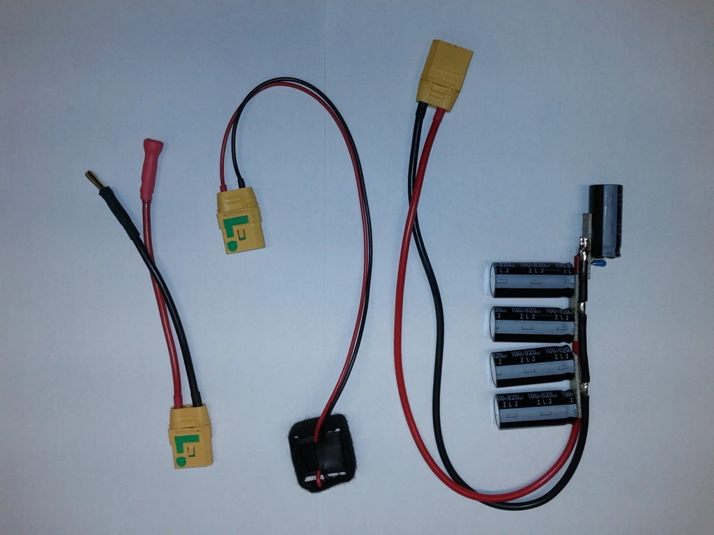
Either way. Here, see gwhy's Inline fuse with anti spark, a very nicely done example with resistor on negative side.

file.php

file.php
 
Offroader said:
Would anyone know if it matters if you use the resistor between the positive connectors or the negative? Everyone shows it on the positive side, but I can't see why it would matter?

I have been using a 1 watt 100 OHM resistor and it seems to work without any issues. I can feel slight heating after maybe 10 seconds.

It doesn't really matter- this just follows the normal negative earth concept for cars and other things. It's just what's expected since the early days when there was positive earth because of the ways people thought electricity flow happened as it appeared that way to them. It's arguably the best bet for new setups as most people unfamiliar with your wiring would expect / assume negative earth now.
 
Speaking from a harness builder perspective... dont use as150. They only work at lower voltages... and barely. I use 300-500ohm resistors in my harnesses for precharge. Suitable for most voltages
 
icecube57 said:
Speaking from a harness builder perspective... dont use as150. They only work at lower voltages... and barely. I use 300-500ohm resistors in my harnesses for precharge. Suitable for most voltages

I don't understand, you're saying not to use a 150ohm but a 300-500 ohm? What would be the problem of using a 150 ohm?

I use a 100 ohm without any problems. Even people posted here that they use a 30 ohm that works.
 
Offroader said:
I don't understand, you're saying not to use a 150ohm but a 300-500 ohm? What would be the problem of using a 150 ohm?

I use a 100 ohm without any problems. Even people posted here that they use a 30 ohm that works.

what's your voltage ?
i use 84v and after testing few ohms 1 watt in the dark, i like the little sparks a 390ohm passes, no need for higher ohms in 84v, but didn't like sparks at below 300ohm, they were strong enough to scorch the contacts, this is how i choose what ohms to use.
 
it seems something is not clear here: AS 150 means 150 amps not ohms. The resistor in the connector only has about 5 Ohm and thats maximum good up to 50V (also depends on capacitance of the caps inside controller). I think up to 100V any resisitor will work that has above 100Ohm and is big enough (1W rating or more). It is no hard calculation what the peak current will be at given voltage. Just use ohms law.
 
http://hyperphysics.phy-astr.gsu.edu/hbase/electric/capchg.html

That link should be of use to people trying to figure out the ideal resistors to use for their setup. To minimize a spark upon connecting the mains, you are probably going to want to get to 2RC (depending on your setup of course).

For a 48V bike, you'll likely be charging a 63V, 1000uF cap (maybe more).

If our goal is to charge to 2RC (~54V) in one second, then a 500 ohm resistor would be ideal. I think that using anything less is just causing unnecessary heat in the resistor.

On the other end of the spectrum, let's assume you need to charge 3 100V 1000uF caps. Using our same guidelines (charging to 2RC, in this case 86V), a 170 ohm resistor would be perfect.

Wattage probably isn't a huge deal since this is a surge scenario. For s**** and giggles, the wattage on that 170 ohm resistor in the 100V setup would be 58.8 watts as time approaches zero!

Edit: Of course, if you are building a pluggable AIO adapter, you probably want to change your charge time down to something like 0.1 seconds or however slow you can force yourself to plug.
 
anon0973923 said:
http://hyperphysics.phy-astr.gsu.edu/hbase/electric/capchg.html
That link should be of use to people trying to figure out the ideal resistors to use for their setup.
Thanks for the link.
The amount of energy dissipated in the precharge resistor to approx 100% capacitor charged, should be 1/2CVsqd.
This energy dissipated (joules) amount should always be about the same for a small resistor, eg time for near to 100% full charge, say 2CR, will be really fast, maybe 0.5S but with large ohm resistors, we have longer time constants.

anon0973923 said:
To minimize a spark upon connecting the mains, you are probably going to want to get to 2RC (depending on your setup of course).
It should depend on what value of spark is acceptable to you with regard to contact damage on your precharge and main contact.
Say an initial state 1A is not causing problems, then in my controllers case 60V/1A= 60 Ohm (62 Ohm standard value)
My controller CR = 4000uF × 60 Ohm = 0.24S, 2CR about 1/2 second current has fallen to negligible milliamps.

anon0973923 said:
If our goal is to charge to 2RC (~54V) in one second, then a 500 ohm resistor would be ideal. I think that using anything less is just causing unnecessary heat in the resistor
.
Looking at the area under the current curve at 1CR, most of energy has heated the resistor, at 2CR might as well approx to 100% of the charging current has passed through the resistor.

anon0973923 said:
Wattage probably isn't a huge deal since this is a surge scenario. For s**** and giggles, the wattage on that 170 ohm resistor in the 100V setup would be 58.8 watts as time approaches zero!
The energy dissipated in the resistor, integrated over your 2CR, you could say it was close to your Isqdt stated, this is what does the damage, depends on the type of resistor used, to what short term punishment it can take.
 
The capacitors look like a short, so the initial current is voltage / resistance. So a 84V system with a 100 ohm resistor will charge at 0.84 amps which is quite low. 10 ohms would charge at 8.4 amps which is still not a large current. With no resistor the current will be MUCH larger. It just isn't very critical.

Regarding the earlier test that burned the 5 ohm resistor. Each charge cycle test needs to be separated by an adequate cooling period. The energy dumped into the resistor is equal to the total stored energy of the capacitor bank, and it takes time for this heat to be dissipated. It is not surprising at all that doing it a few times in a row will overheat the resistor. For example with an 84 volt system and 100 ohm resistor the initial dissipation is about 65 watts. It decays quickly but still is a lot more energy than the small resistor is designed to handle. That works only if you don't do it often. Changing the size of the resistor doesn't change the total energy, only the capacitors affect that. But it does stretch the pulse and make it longer, however it won't be long enough to help the dissipation, the resistor must absorb the entire decaying pulse and dissipate it later. Thus using a larger resistor will help as it has more thermal mass to absorb the pulse. Ideally pulse rated resistors would be used. But any resistor that doesn't fail is probably adequate.
 
I was thinking how i could make a precharge resistor, i cut down a large pencil graphite section and pushed fitted it into the end of my 5.5mm bullet, it was sticking out about 4mm and measured about 3.7 Ohms from the bullet to the graphite tip, need to make it more, about 10mm, should give close to 10 ohm.
My controller operating current never exceeds around 20A, so inserting the bullet right into the connector, is not really a problem, due to the gold coating and current carrying across the connector is more a function of the outer circumference of the bullet and the force on the connection, the inserted overlap is a secondary.
Initial current will be about 6A, if i touch it against the side of the connector first, it should reach 5CR, eg fully charged in 0.2 seconds.
 
Alan B said:
Regarding the earlier test that burned the 5 ohm resistor. Each charge cycle test needs to be separated by an adequate cooling period.
you have absolutely right, but i had the situation that the AS150 with 5 ohm resistor worked two or three times with days in between and the third time it died and there was an unexpected big spark. there reason probably was PARTIAL DAMAGE of the resistor (to low watt rating).
because of this i made sequently charge cycles to find out if its bullet proof or not ;)
 
Back
Top