methods
1 GW
An associate who has embraced the revolution completely asked me to convert these single cell BMS units from a 3.3V to a 3.7V chemistry.
EDIT: Done - see this post: https://endless-sphere.com/forums/viewtopic.php?f=14&t=88312&p=1288762#p1288762


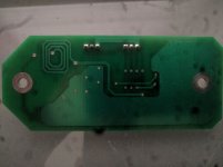
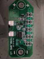
I have not researched the boards yet... but a quick visual inspection reveals a lot.
Only question is if a divider change will do it (doubt it) or if those 5 pin parts are of interest. I at first thought the 5 pin parts were one and the same that Fechter suggested for one of my LVC/HVC modules... but ... one will do both LVC and HVC and the board has 2 so...
First glance notes:
The 8 pin gullwing dip is obviously an optocoupler output.
Wondering about that swirl of traces.... some kind of choke attempt?
TVS diode and 10V clamping zener are obvious
10pcs bleed resistors are obvious
Current limiting resistors for the Opto are apparent
LVT diode being current limited by the opto photo and resistor to V+
HVT diode with current limiting resistor next to it turned on with shunts
Bypass caps for the 5 pin detectors
Nchannel fet to turn on the bleed resistors, Source on Negative, Collector on shunts to Positive, gate heading over to HC detector with a pulldown
Broken down left to right top to bottom:
Positive Terminal
10pcs balance resistor in series parallel
TVS and 10V clamps
LC and HC part numbers? (I suspect I have a roll or two of these around...)
C1's are the bypass caps - probably 0.1uF
LVT standard with the cathode to the left
R332 probably a 10K pulldown for the gate
10R is the limiter for photo diode and LVT diode
8 pin is standard opto with standard pinout I presume - raw diodes requiring 200 to 500 ohms
Pin headers along bottom in parallel for pass-through open collector outputs
R471 bottom grabs the switched end of the shunts and limits for the photo diode only
R471 top limits for the HVT diode only from V+ to Collector in parallel with the shunts
PZTC standard nchannel
Negative terminal
Yep - so I see no divider
In order to change the chemistry on this bad boy to 3.0V to 4.2V I need to swap the two 5 pin parts
A quick glance at my existing data sheet should indicate which to switch
Maybe he doubled them up to handle extra current... or...
Maybe he mixed and matched to get a desired HVC and LVC that were not available (more likely)
Anyhow... for this deliverable... which is retrofitting old 24V lead acid lawn mowers to 8S EIG... I will likely just spin a new low cost board based on all we have learned.
I owe the community V2 of my mosfet based completely isolated SSR... so... will integrate.
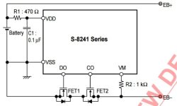
Same design as seen below (no uController, hardware based, super simple)
I will add to the LVC section a gnarly array of 4110's for cutting discharge
I will add to the HVC section a gnarly array of 4110's for cutting charge
Issues to address are HVC latch (solved slowly by bleed resistors...)
Issues to address are LVC latch (no solve)
With the 4110's ganged on output one must be careful that they are both on or both off unless you want to utilize the body diode which is ill advised... so a hard tie between their gates is safest... but then you need onboard smarts to beat latch condition... so.... body diode conduction it is to get out of HVC and LVC latch conditions (4pcs 4110 short period of time de-latch)
Yea... If HVC latch hit a moment or two of loading through body diode should unlatch and flip that mosfet back on
LVC latch will take a few moments of charging
Would rate for 100A burst charge or discharge 10 seconds
40A continuous ... charge or discharge... so ... going to need to use a different fet or array of fets or heat sinking
Just brainstorming at this point
I do not like the "1 cell BMS" for most applications. Its great for huge 90Ah cells in a car but no good for smaller setups.
Best to gang 6 channels together. 4 or 6 or 7 or 8... whatever fits
Allow them to stack to a REASONABLE level. 30V... cheap. 100V - a bit more expensive. Not interested in anything high voltage at this point... but may well just make it expensive right? 200V? 300V?
To make them programmable I could populate the boards with 2pcs HVC chip and 2pcs LVC chip with a jumper. Select-a-chemistry. That keeps the nasty uController issues out of it and makes for a hardware solution.
To shunt current MUCH faster the heat sinking for the LVC and HVC switch can be utilized with another heavy Nchannel and much larger resistors maybe 2W... so 2W/4V= 500mA. 2W * cell count = manageable.
Or... Maybe none of this
Maybe it is time to simply make a 2 step charger.
BULK charge at 20A up to 90% charge terminating on any cell HVC
Trickle charge via Xpcs 4.2V DC-DC isolated super small low current mosfet controlled off the pack voltage (nope - wont work below 60V)... so powered off the charger DC (nope) ... so powered off the AC such that a user can plug in and grab a very quick 90% or first HVC ... then if they leave it in user gets a balance charge to complete HVC on all parts... side effect being battery only used to 90% most of the time.
I would like to work in the isolated coin cell aspect... so... going to separate out the Charge/Discharge section from the per cell detection open collection section... then it can control any voltage in any direction up to the rating of the mosfets with no interaction with the control section what so ever. Yep... thats it
One board
4 or 6 or 8 individual isolated detector circuits
Detectors ganged open collector via opto's (MUST ADDRESS THE LVC RUNAWAY SITUATION!!! WHERE LVC TRIPS THE OC OUT DRAWING BASE CURRENT)
gang all the parts on the board after the optos
send out to switch board which is powered from the overall pack via a big inline resistor and a zener (easy) or by coin cells
But... then as LukeMan pointed out in an argument the other day... I am 2-3 years behind on development.
Perhaps I am inventing a wheel which already turns just fine. how about those chinese BMS's - they good yet?
This project is only being taken on to fulfill obligations to those who invested in my cuttout board a long time ago (before Methods Technology crashed and burned in a flaming epic way) and for Doug... who has worked so hard to bring the ELectric REvolution to so many people.
Input is welcome
The best input is not what you specifically need for your specific setup
The best input is what you think the most people could benefit from
I will make the boards as cheap as humanly possible
I will do the entire development open source (which means it takes twice as long... because its an equal time writing as it is engineering)
I will solve the Cheap Chinese latching conditions (if they are not already solved)
I will include hardcore LVC and HVC cut with power levels that are worth noting
I will include balancing which is aggressive - one can populate to suit depending on ability to sink heat... I have a thousand TO resistors that bolt to a heat sink laying around
I will make the switching section separate and available as I owe at least 3-10 people a free upgrade... so I will lay pads for the coin-cell original as well as a resistor to zener constant bleed
I am thinking the board needs a single uController (running Arduino of course... in low power mode) to disambiguate the latching condition - if I do so I can solve the latching by allowing bust currents or some sort of smarts... where the arduino reads the LVC and HVC open collector stackup and makes a decision... with a timeout... allowing a little burst-burst to break it out of lockup... allowing users to fiddle-diddle.
It will not be programmable as that leads into all the Linear Tech and other chips designed for this... they are expensive... but fewer parts... all require a micro controller and fancy communication... do I want to go through all that again? meh... maybe... lots and lots of 5 pin parts on the board get hard to bake on.
Hmmm... Open to suggestions.
This is a 1-2 hour per week engagement as I literally am collecting cans for money to buy Thunderbird in 40oz that I drink in the bushes with toothless homeless men and woman while getting an awesome sunburn and pooping my pants from time to time. (inside joke.. that is funny... but not really... I grew up in Santa Cruz)
-methods
EDIT: Done - see this post: https://endless-sphere.com/forums/viewtopic.php?f=14&t=88312&p=1288762#p1288762


I have not researched the boards yet... but a quick visual inspection reveals a lot.
Only question is if a divider change will do it (doubt it) or if those 5 pin parts are of interest. I at first thought the 5 pin parts were one and the same that Fechter suggested for one of my LVC/HVC modules... but ... one will do both LVC and HVC and the board has 2 so...
First glance notes:
The 8 pin gullwing dip is obviously an optocoupler output.
Wondering about that swirl of traces.... some kind of choke attempt?
TVS diode and 10V clamping zener are obvious
10pcs bleed resistors are obvious
Current limiting resistors for the Opto are apparent
LVT diode being current limited by the opto photo and resistor to V+
HVT diode with current limiting resistor next to it turned on with shunts
Bypass caps for the 5 pin detectors
Nchannel fet to turn on the bleed resistors, Source on Negative, Collector on shunts to Positive, gate heading over to HC detector with a pulldown
Broken down left to right top to bottom:
Positive Terminal
10pcs balance resistor in series parallel
TVS and 10V clamps
LC and HC part numbers? (I suspect I have a roll or two of these around...)
C1's are the bypass caps - probably 0.1uF
LVT standard with the cathode to the left
R332 probably a 10K pulldown for the gate
10R is the limiter for photo diode and LVT diode
8 pin is standard opto with standard pinout I presume - raw diodes requiring 200 to 500 ohms
Pin headers along bottom in parallel for pass-through open collector outputs
R471 bottom grabs the switched end of the shunts and limits for the photo diode only
R471 top limits for the HVT diode only from V+ to Collector in parallel with the shunts
PZTC standard nchannel
Negative terminal
Yep - so I see no divider
In order to change the chemistry on this bad boy to 3.0V to 4.2V I need to swap the two 5 pin parts
A quick glance at my existing data sheet should indicate which to switch
Maybe he doubled them up to handle extra current... or...
Maybe he mixed and matched to get a desired HVC and LVC that were not available (more likely)
Anyhow... for this deliverable... which is retrofitting old 24V lead acid lawn mowers to 8S EIG... I will likely just spin a new low cost board based on all we have learned.
I owe the community V2 of my mosfet based completely isolated SSR... so... will integrate.
Same design as seen below (no uController, hardware based, super simple)
I will add to the LVC section a gnarly array of 4110's for cutting discharge
I will add to the HVC section a gnarly array of 4110's for cutting charge
Issues to address are HVC latch (solved slowly by bleed resistors...)
Issues to address are LVC latch (no solve)
With the 4110's ganged on output one must be careful that they are both on or both off unless you want to utilize the body diode which is ill advised... so a hard tie between their gates is safest... but then you need onboard smarts to beat latch condition... so.... body diode conduction it is to get out of HVC and LVC latch conditions (4pcs 4110 short period of time de-latch)
Yea... If HVC latch hit a moment or two of loading through body diode should unlatch and flip that mosfet back on
LVC latch will take a few moments of charging
Would rate for 100A burst charge or discharge 10 seconds
40A continuous ... charge or discharge... so ... going to need to use a different fet or array of fets or heat sinking
Just brainstorming at this point
I do not like the "1 cell BMS" for most applications. Its great for huge 90Ah cells in a car but no good for smaller setups.
Best to gang 6 channels together. 4 or 6 or 7 or 8... whatever fits
Allow them to stack to a REASONABLE level. 30V... cheap. 100V - a bit more expensive. Not interested in anything high voltage at this point... but may well just make it expensive right? 200V? 300V?
To make them programmable I could populate the boards with 2pcs HVC chip and 2pcs LVC chip with a jumper. Select-a-chemistry. That keeps the nasty uController issues out of it and makes for a hardware solution.
To shunt current MUCH faster the heat sinking for the LVC and HVC switch can be utilized with another heavy Nchannel and much larger resistors maybe 2W... so 2W/4V= 500mA. 2W * cell count = manageable.
Or... Maybe none of this
Maybe it is time to simply make a 2 step charger.
BULK charge at 20A up to 90% charge terminating on any cell HVC
Trickle charge via Xpcs 4.2V DC-DC isolated super small low current mosfet controlled off the pack voltage (nope - wont work below 60V)... so powered off the charger DC (nope) ... so powered off the AC such that a user can plug in and grab a very quick 90% or first HVC ... then if they leave it in user gets a balance charge to complete HVC on all parts... side effect being battery only used to 90% most of the time.
I would like to work in the isolated coin cell aspect... so... going to separate out the Charge/Discharge section from the per cell detection open collection section... then it can control any voltage in any direction up to the rating of the mosfets with no interaction with the control section what so ever. Yep... thats it
One board
4 or 6 or 8 individual isolated detector circuits
Detectors ganged open collector via opto's (MUST ADDRESS THE LVC RUNAWAY SITUATION!!! WHERE LVC TRIPS THE OC OUT DRAWING BASE CURRENT)
gang all the parts on the board after the optos
send out to switch board which is powered from the overall pack via a big inline resistor and a zener (easy) or by coin cells
But... then as LukeMan pointed out in an argument the other day... I am 2-3 years behind on development.
Perhaps I am inventing a wheel which already turns just fine. how about those chinese BMS's - they good yet?
This project is only being taken on to fulfill obligations to those who invested in my cuttout board a long time ago (before Methods Technology crashed and burned in a flaming epic way) and for Doug... who has worked so hard to bring the ELectric REvolution to so many people.
Input is welcome
The best input is not what you specifically need for your specific setup
The best input is what you think the most people could benefit from
I will make the boards as cheap as humanly possible
I will do the entire development open source (which means it takes twice as long... because its an equal time writing as it is engineering)
I will solve the Cheap Chinese latching conditions (if they are not already solved)
I will include hardcore LVC and HVC cut with power levels that are worth noting
I will include balancing which is aggressive - one can populate to suit depending on ability to sink heat... I have a thousand TO resistors that bolt to a heat sink laying around
I will make the switching section separate and available as I owe at least 3-10 people a free upgrade... so I will lay pads for the coin-cell original as well as a resistor to zener constant bleed
I am thinking the board needs a single uController (running Arduino of course... in low power mode) to disambiguate the latching condition - if I do so I can solve the latching by allowing bust currents or some sort of smarts... where the arduino reads the LVC and HVC open collector stackup and makes a decision... with a timeout... allowing a little burst-burst to break it out of lockup... allowing users to fiddle-diddle.
It will not be programmable as that leads into all the Linear Tech and other chips designed for this... they are expensive... but fewer parts... all require a micro controller and fancy communication... do I want to go through all that again? meh... maybe... lots and lots of 5 pin parts on the board get hard to bake on.
Hmmm... Open to suggestions.
This is a 1-2 hour per week engagement as I literally am collecting cans for money to buy Thunderbird in 40oz that I drink in the bushes with toothless homeless men and woman while getting an awesome sunburn and pooping my pants from time to time.
-methods


