Sorensen DCS Series - Modification and Repair Thread

Hmmmm....
Thanks for the history.

When I was in school it was around 2000.... so... we covered legacy tech but had to CRAM in all the new tek. I never had much reason to re-visit as AC (other than house wiring) never really came across my desk.

...

When I get back on this I will investigate -
as the documentation says it voltage doubles based on P1 position for the Power AND Bias sections of the circuit...

And their "ain't no power transformer, far as I can tell" :(

So I am guessing this could be what was done
It would be ~1KW rated

... It will give me reason to reverse engineer that section of the PCB... so just as well.

(I obviously know how to put together a half or full bridge - but this is the first I have heard of a multiplying bridge...

... At least under that name ...

I am aware of a: cockcroft walton voltage multiplier
Which I suspect may be similar in operation.

-methods
 
Ok... I have 20 minutes to learn about voltage doubling rectum-frierz....


-methods
 
Ok - there is just no misinterpreting this:

For 230Vac operation, rectifier CR35 and filter capacitors C32(A,B,C) and C72(A,B,C) are
configured as a full wave bridge.

Ok - full bridge rectum-frier

For 115Vac operation the input voltage selector P1 is
configured so that CR35, C32(A,B,C) and C72(A,B,C) form a voltage doubler.

This I did not anticipate - voltage doubler

In this manner,
the rectified DC voltage is always within the range of 225-350VDC with either a 115 or 230Vac
input voltage. In addition to determining the input rectifier configuration, P1 also configures the
connections to the primary of auxiliary transformer T4 for series or parallel operation

We are reading 150VDC
So we have certainly found our problem.

...

Troubleshooting Procedure:

1) Try not to take the PCB out of the housing (just ... so much work)
2) Look up the datasheet of the Rectum-Frier
3) Attempt to measure the diodes in the circuit (Sometimes works, sometimes not, depends on parallels)

0) First - probe as much as we can to draw the Full Bridge and Doubler configurations

...

This may be one of those deals like changing the transmission in a car...
YEA - you can do it without dropping the motor.
Takes about 13 hours

OR

You can hoist the entire assembly out in 45 minutes and just pop it off

sigh...

Ok - the right thing to do is to pop the PCB... as there may be something VISUALLY OBVIOUS at the bottom of the board... like a simple cracked trace.

Off to do that now
I am quite certain that we are converging on the solution.

1) Blown out rectom
2) Blow out doubler caps
3) Broken conductor someplace

... There is a big clue in that the output reads the same in both P1 configurations. I am certain that if we pondered that the answer would become apparent ...

...

meh
Pics when I have the PCB board out :mrgreen:

-methods
 
Lol - took all of 5 minutes to remove the PCB.
The fan and the heat sinks are cantilevered.... :?

Cheap Bastards :!: :mrgreen:

...

Damn buggy Photo and Picture resizer (Android...)
Duplicates pics and drops pics :roll:
Here is what transfered:
.
.

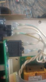
20180725_170205-1494x2656.jpg
Color code your wires

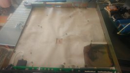
20180725_170502-2656x1494.jpg
Rectum-Frier is dry but with a pad
Watch the washer and the nut

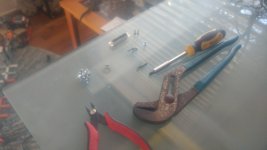
20180725_170630-2656x1494.jpg
I did the job using only these tools
Cuttiez were used as tweezers to grab the bits
Locks were used for the Dsub25 and Rectum
1 flathead on my AC wires
2 long Philips go in the back right - watch the insulating washer , second is captured
Listen for dropped parts
one bolt has no washer, it is captured (a ground)


View attachment 7
And there it is...
Bent over for your viewing pleasure
Please only look - dont touch. If you want to touch you need to go to the Champagne room. There you will pay $300 and leave frustrated. I suggest wearing sweatpants.

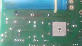
20180725_170849-2656x1494.jpg
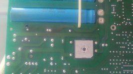
The burnt FR4 is under the 5W 10K resistors
They are in series
One across each cap, center tapped
Its just heat damage

View attachment 5
View attachment 4
More heat over here (surprise... )
To be expected

20180725_170925-2656x1494.jpg
20180725_172415-2656x1494.jpg
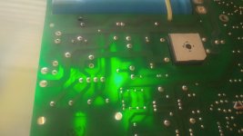
You use a flashlight to expose 2 layer boards
Sometimes even 4 layer

You look at only the heavy traces. Ignore the small traces

20180725_172810-1494x2656.jpg
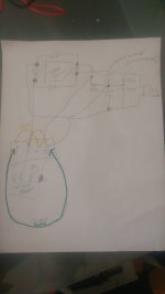
This is a VERY ROUGH first cut mapping of the heavy traces
Sadly I am reading 4 diodes... but I have yet to pull the part datasheet
Note the odd 60 ohm resistor...
note the center tapping... This will be interesting to re-draw

The big caps are in series - as we learned in the video
They have 10K bleeder resistors, assume 150V each, have not checked their rating

Need to test the caps
Traces all look ok

Need to draw the circuit in both P1 configurations

Confirmation that P2 is just the Caps... so.... GO AHEAD AND SHORT THOSE PINS.

20180725_172831-1494x2656.jpg

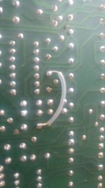
I had a bunch more pics showing Production re-work
Actually... it is not all rework. The caps and such (other side) are rework - because they could have been placed.

The jumpers are solutions to NetList conflicts. Sometimes it is just easier to have slave labor solder 1 million jumpers than to do it right :)

Now... if it were not an afterthought... the jumpers likely would have ended up as trimmed and precision bent "parts" or Zero Ohm resistors. Cutting and stripping little leads is bullshit. I know... know how???

and onward

-methods

P.S. 13th pic got dropped. 8' waves at the lane. Gonna go down to SeaBright and get shore-pounded. The lifeguard left - so I can be left alone to my mission. Yesterday a lady went out into a BIG SET... the boy and I were down there digging. She had no wetsuit, no fins, and 2 sets came in while she was out. Your only choice is to swim OUT when it gets hairy (in equals broken body parts). Problem is - you have about 5 minutes in that water unless you are conditioned or ... have body fat. Maybe not this time of year - but I almost drowned a year or two back. The cold takes away everything you have... just like major body damage...

Hollywood is TOTAL BULLSHIT.
Magazines never empty, broken bones dont stop them, they never die.... yea... RIGHT.
 
Next step (if you want to be cool guy) would be to go over the top and bottom of the PCB boards and super-impose parts so that the unfamiliar can more easily trace the schematic to the hardware.

I am old school and like my Schematic to (at least in some way) match the physical layout. This often results in many crossed wires... as with a PCB... you have 3 layers. Most folks try to draw schematics with no crossed wires. Makes no difference to me.

If we were all horny we could re-flow all the solder joints - flux them first and clean them after.
Not going to happen

...

I would like to test the caps
Basic quick math tells me

300V / 20K = 15mA

So to test them... you will need more than that.
My rough math shows that it is precharging at 250mA
Thats assuming 1.2K for the inrush resistor

You use tow (RC time constants... read this)
http://hyperphysics.phy-astr.gsu.edu/hbase/electric/capchg.html

I took a guess at 300V, 500uF (remember to halve the capacitance in series), and 1.2Kohms
Shows it charges up in about 600mS (sounds sane)
Call it "less than a second" with bleed

We could calculate that-but we dont care
Those are small traces
Small traces can be cut off the board :mrgreen:

...

SO anyway -
Your best bet to precharge those bad-boys is to go thru the existing precharge resistor
Be careful... as applying back-voltage (especially high voltage) can cause all sorts of trouble.

Your goal is to charge them up
Then time the discharge
Then calculate the capacitance

Confirm the values before doing so
Confirm other parasitics

HOW would they behave if shot?
Meh.... I imagine they would have an order of magnitude less capacitance. They are wet caps. If they go dry then you dont get any electrons flowing around... therefore... they are basically cardboard with metal between them

RiGhT?

(See... it is all simple... you just have to slow down enough to think about it)

-methods
 
so - you can prechage them by just turning on the supply.
There is no active discharge... IF... you remove the fuse next to them
That fuse goes to next assembly (pic got missed... grr....)

With no load (or relatively no load) on the circuit (This can be measured for DC - just ohm it with empty caps) it will obey the formulas. You dont time it until it goes to zero - just watch it until the rate of change flatens out

1) Turn on supply
2) Remove Fuse (You just touched 150V DC... so... pay attention and swap steps 1 and 2)
3) Apply cheese-dick DMM set to VDC
4) Turn off supply and observe

Before you get out hour glasses and nuclear clocks...

DId it just bottom out???
It should take a wile - just plug the 20K inito the formula to guess at it
Should be order of magnitude... so 10 seconds

If they bottom out - caps are bad
If they take about 10 seconds - caps may be good

:x

Simple gets it done

If you dont have an ohm meter just lay your herpe pimpled tongue on there and have someone else count in thousands until you stop screaming. That should do it.

Can you grow herp on a tongue?
Jesus... I read you can get herpes in the cracks of your fingers and all sorts of places

Herpes is the primary reason that I only got laid by 20 or so girls in my youth. I was terrified of catching an STD!!!!
You should be to

The only thing worse than smoking ciggies... is catching bumps and spreading them around.
So... wrap it up buddy (or have him wrap it up)

-methods
 
Ok - I have a minute
.
.
RectifierTheory.jpg
.
.

Further parsing that

(Remember... I am doing 25 other things and sneaking this in from time to time. Time-slicing to this degree results in in-efficiency... as I have to refresh RAM and Virtual Memory from encrypted hard drive... as this is NOT what I have cooking in my thinker.)

* Full Wave Bridge used on 150V, 200V, and 600V models (So what is used on lower voltage modules???)

* They reference 8V configuration... that refers to the output of the configurable transformer... which we dont care about

* CR300-CR307 seems like a range of a part named CR30X... where higher number means higher voltage?
mmm... no
CR301-CR304 is used on the lower voltage units
CR300-CR307 is used on the higher voltage units... meh... I am thinking that may be a typo... who makes a part number that looks like that?

... We get out our tool... OCTOPART

Nothing on Octo...

Now we pump Google with things like: "AC Full Bridge Rectifier CR300"

AH HA - Typo

I have hits for a CR300-200R
So... typo on the repeat CR
So... reforming query (this really is where the magic is... knowing how to find what you seek... WITHOUT HELP)

(Its what we expect from a Jr Engineer... you better show up with search skills... as I dont need you to do any particular job... I need you to FREE ME UP so I can do other, more difficult, more complicated, longer lay-up jobs... ya know?)

so - using our random Google findings (and it is always 2nd or 3rd order stuff... that leads us to what we seek...)

Lets try: CR300-307
grrr.... type type type...

hit this
https://www.diodes.com/assets/Datasheets/products_inactive_data/ds26003.pdf

not it but converging (at this point I am looking for pictures... should go check the physical part for any clues...)

A big clue is that the only hits I am getting are direct hits to the manual I am sourcing from.
At this point it may make more sense to back off and just search AC Rectifiers in similar packages... then work backwards

(Its an old package - they do it different now - so this will be a bit harder...)


OK: "AC Full Bridge Rectifier"
(on Google)

Gets me a hit that looks like the same package
Same mounting hole
Same pin 1 indicator
History tells... that these are often pin compatible... and of similar power ratings

I hit this
https://www.mouser.com/ProductDetail/ON-Semiconductor-Fairchild/GBPC15005?qs=UFhdRzUoebVsIISr4%2FCJ8A%3D%3D&gclid=EAIaIQobChMI3oWQsv-83AIVUYF-Ch3ORw95EAQYAyABEgJtKvD_BwE

Which MAY or MAY NOT be pin compatible
(It may not even be the same kind of device - certainly may be a different voltage rating... but we are converging... we can get a list of suppliers... looking for key words like:_)

* Pin compatible with
* Replacement part for
* ....

As we are searching a legacy part remember....

So you would be looking for this in their promo paperwork, datasheets, website (using advanced search across a domain)

ah - this is what we seek


Ok... AC INPUT
DC OUTPUT

That makes sense right?
All we have to do now is see if that jives with what we measured and drew

REMEMBERING

That we have TOP VIEW, BOTTOM VIEW, PCB VIEW

DO
NOT
MIX
THOSE
UP

They are quite different ***

But in this case - we know that DC+ must go to the top of the caps
DC- must go to the bottom of the caps
AC is dont care and heads back toward the AC

Onward....

-methods
 
Confirming with the drawings:

1) Cut corner goes to DC+?
Yes

2) Opposite corner goes to DC-?
Yes

3) AC to the other two pins???
True

NOW...

What is P1 doing to that?

well... based on my jank drawing:

A) The 240V Jumper does nothing to the rectum-Frier - it appears to mostly be doing work on the step-down transformer.

So ... if we are putting in 240VAC RMS
240VAC RMS / 0.707 = 340V Peak

So our rectified (Ideal) out put would be an averaging of 340V Peak - so less than that.

the rectified DC voltage is always within the range of 225-350VDC with either a 115 or 230Vac
input voltage

Less than 350? Yep
Ok - so the bridge in "Standard Configuration" jives with our expectations

I have not read the bridge directly with 240V input (Thats a major to-do.... and should have already been done... DOH)

We know it is not multiplying because we are reading 150VDC
WAY below expectations

B) The 120V Jumper

* Links an AC input to teh center of the cap stack
* The second of the two loops appears to act on the step down

(So - perhaps the 4 pin jumper has 2 tasks, both separate:)

Pin 1 appears to act on the step down
It can go to pin 3 or pin 4 - and this has no effect on the voltage doubler config

Pin 4 appears to act on the step up
It can have no connection... or it can go to pin 2

Now its time to draw both circuit configuration
(6yo climbing on my back... wife saying its time to take a walk... 35 emails in the queue.... sigh... when I get back)

-methods

** Remember - we are just trying to share methods and ways... a formula that can be repeated... using tools and materials which are available... to set up an international experiment... that can be repeated...

*** E-Waste should be shipped to someone who will fix it - not torn apart for raw materials

**** Products should be designed to last and be repaired and upcycled... not to be thrown away... it is the cowards who seek profit in the short term who spec things that quickly become garbage... design your equipment to LAST and you will be remembered
 
120VAC RMS / 0.707 = 170VAC Peak
eh - yea - that makes sense

So - with the 120V config we are in standard mode
This indicates that our jumper is not acting on the circuit

Powering the unit and poking the jumper in and out could (blow up in your face) or indicate this.

Its time for testing of the jumper
Measure (at the rectum) whether or not the short is being applied

*** remember ***
That with or without the output caps... we WILL see something close to the AC peak input on the output (with no load)

So caps or no caps
We aint seeing doubling
We are seeing standard rectum

BUT

Caps ARE required for doubling. Looking at any of the diagrams you can see that the cap-stack charges one way, then the other cap charges the other way, then you sum the cap voltages.

This is a very different principle than the standard HUMP HUMP HUMP "routing" that a full bridge does.
Veeerrrryyyy different principle

You need a LOT of cap to do this doubling*

They have to smooth out a KW of thruput with minimal dipping
(or not - it is only going to get chopped next... and the chopper is PWM with feedback... so it may not really care what is coming in)

Anyway

-methods
 
So does the AC line go right to the bridge rectifier (well, after going through some filters, fuses, etc.)?

Measure AC across the input terminals of the bridge when on and verify voltage there. Measure DC across the caps and see if it looks like it's in the right ballpark. Then measure AC across the caps. This should be millivolts just from the ripple. If you see a large AC voltage across a cap, it's a way to tell it's open circuit or dried out.
 
Previously I measures SIGNIFICANT AC voltage across the caps.
50V IIRC
.....

Thanks Fechter!

... And I was over here pondering that 60 ohms... Wondering if it was large or small... Cuz there are no 60ohm power resistors...

...

Fechter has the right idea.
Most likely failure mode of a switching circuit like this that has many hours is dried out caps.

...

Now we go to our parts bin....
And do a real simple test...

Does wiring up a big 400V cap in parallel get us any difference in our dc output?
... I think, due to the center tap, that it MUST be 2 caps in series - for the stacking method to work...

So... Maybe I need a couple 200V caps...

Time to dig around and experimentaly test for the "short circuit solution"

-methods
 
See...
This is why we need old guys around.

The guy with hair coming out of his ears wrote 3 sentences.
The kind that come from experience and never are really spelled out in a book.

I suppose they are common sense - but - not for me... since I did not have significant direct experience.

Yea...
I guess that much capacitance
In a no load configuration
Should settle to (converge on)
Very little ripple.

I would not have guessed mv
Not even hundreds of mv
Even a few volts sounds reasonable
...

But I am seeing FIFTY VOLTS
... a quarter or a third the source...
No load

...

Sounding good!

*

Off to build construx since F solved the riddle.

-methods
 
In a doubler configuration like that you might see higher than normal ripple, but with no load should still be under 1v. Caps don't like heat and there are signs of excessive heat. You could parallel additional caps just for testing but try to keep both of them equal.

Fechter rule of troubleshooting #4: Always check the parts that are the easiest to replace first.
 
So we need something that will stack up to be

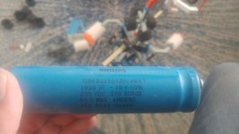
900uF @ 400 working volts rated to 500V with a center tap
(So two stacks that add up to 1.8mF each and are rated for 250V)

Note the difference between the working voltage and peak voltage
(Thank you video.... you should watch ALL of his videos...)

.
.
.

20180726_105500-2656x1494.jpg

..
..

..

(And I say stacks because these days it is much more common to find arrays of caps than big caps. I can no doubt order them on Digikey right now and have them tomorrow. Lace them together or maybe even lay out a PCB for them)

The Alternative...

Is to try and find something which is the exact same fit, form, function...
Not too tall
Not too long
Not too wide
Similar mounting posts... sigh...

I will give it a go - but I am almost certain that I will have to substitute.

...

Of course we will buy the highest quality - as these are really the only major wear items (other than the fan)...

... Wish I had my Fluke instead of this shit-dog AutoZone meter :cry:
Do a quick capacitance check :D
...

Time for a "Ghetto Capacitance Check"
RC Time Constant...

How duz you figerz the Fluke measures the Cap without charging it up?
Maybe injects a frequency sweep (not likely)
Maybe ... watches for a roll-off? (eh... it would have to charge it up... its not doing that...)

Have to look it up and see :idea:
I have never made my own basic LRC Meter
Maybe it just switches in inductance and looks for balance? (nope)

... Maybe a Capacitor Surf Board >>>

-methods
 
Google hits Octo @ $25 each - who knows about quest... have not used their service yet

https://octopart.com/3186bg182t200ama3-nxp+semiconductors-78748801

-methods
 
FYI: I dont have a good feeling about ANY of those parts from ANY supplier which is not quality (Digikey and Mouser support quality)

New-Old-Stock is usually great...
For big buckets of power resistors

For electrolytics New Old Stock can be a big gamble.
If they were stored in a cool dry place - no doubt you can get some work out of them.
If they were stored in Arizona for the last 20 years... eh...
You may get some service out of them (because thats cooler than in a powered supply likely...)
But you will not be getting $20 bux worth

As for replacement or knock-off.... same sort of risk.
OEM runs back in the day were limited
They may have made 200,000 to a given spec
They still have the tooling around... but that does NOT MEAN that they are using the original spec!

Different materials
Different quality standard
Different process
Different different different

(mostly talking about replacing mil spec stuff with knock-off... like replacing your 58 Chevy original parts with "new" parts... which are mostly electroplated plastic... instead of actual metal)

...

Now to search by spec instead of part number
Another good idea is to slowly back off the part number until you hit something... as the last few digits are usually SUPER SPECIFIC...

Example:

123-ABC Part

It comes in the

123-ABC-01
123-ABC-02
123-ABC-07

Where the 1 and 2 are most common
Where the 7 is special order... maybe because it has longer leads... or different markings... or... an elevated rating (tighter screening)

So - we back off the last digits to find the core part - which may be VERY COMMON and could be 1/10th the cost of the spec-part.
The spec part, in a commit buy of 200K pieces may have only been 1% more expensive... but now... its scalper prices for those... as some people are required to repair 1:1 to maintain previous validation etc.

...


3186BG182T200AMA3
3186BG182T200AMA
3186BG182T200AM
3186BG182T200A
3186BG182T200
3186BG182T20
3186BG182T2
-methods
 
No luck - so off to spec

For caps this big I suggest looking for working voltage instead of burst
(as a 250V cap in the same capacitance as a 200V cap will either be much bigger or much more expensive. Compact is expensive)

https://www.google.com/search?rlz=1C1OKWM_enUS789US789&ei=IhBaW9HsBqrT0gK9xpOADA&q=1800uF+200V&oq=1800uF+200V&gs_l=psy-ab.3..0i22i30k1l3j0i22i10i30k1j0i22i30k1.5697.12250.0.13534.11.11.0.0.0.0.112.1020.9j2.11.0....0...1.1.64.psy-ab..0.11.1020...0j0i131k1j0i10k1j0i30k1.0.uRqZmFnLRoM

-methods
 
fechter said:
In a doubler configuration like that you might see higher than normal ripple, but with no load should still be under 1v. Caps don't like heat and there are signs of excessive heat. You could parallel additional caps just for testing but try to keep both of them equal.

Fechter rule of troubleshooting #4: Always check the parts that are the easiest to replace first.

Missed this - was yapping from phone then computer

Yea - the zip-tie on the caps hand melted off
Right next to one of them was a 10W heater :shock: :shock: :shock:

I bet the one next to the heater is more worn than the other...

-methods

P.S. For more reason than one... Fechters rule makes sense... good engineers make it easy to replace parts that wear :!:
So look there first

SWEET
 
Good engineers seem to be in really short supply these days. Try working on any German car.

Time for a "Ghetto Capacitance Check"
I used to charge them up with a power supply, then short it with a screwdriver and see how big the spark is. No spark = bad cap.

It should be fine to substitute higher voltage or higher capacitance parts as long as the pair are matched. Caps like that are quite expensive. Making one from a bunch of smaller, cheaper ones is not a bad idea.
 
I like sparkles . . .

I have been angling to get one of my employers to try shorting two EV size batteries thru a standard 500A contactor. Maybe a 200V Zero monolith vs a 420V Tesla.

No fuses of course. . . as I anticipate a lot of "shitty fixes" and "rigged setups" as EV's start hitting the "diy AutoZone mechanic" crowd.

Who wants to pay $50 for a properly rated charging fuse when a short piece of copper costs $0.50? I know I have done it - as have many.

We won't be able to depend on OEM's to ensure compliance to standards... Once the cars break, get sold used and as parts... Its going to be "wild west".

-methods
 
Ok - caffeinated and have a minute while laundry finishes (work day)

Time to redraw RectumFrier in both P1 configurations
This is officially the first learning-extraction from the reverse engineering process
(As I have never drawn a rectifier based AC voltage doubler)

...

The way I justify the hours (10's then 100's then thousands... if you are around long enough) dumped into projects like this is tuition-offset.

If I were to monetarily value my efforts into repairing a $600 power supply at my Engineering Rate it would be a monumental failure. . . as opportunity cost blows this out of the water. Thats part of why I constantly clown on folks who set financial reward as their metric for success.

Our metric here is "New Learnings" - which can be worth NEGATIVE $$$ all the way up to Infinity $$$

Example:
"I learned how to smoke crack!" --- (Negative return on investment)

Ultimate example... is 3 years down the road I am contracting somewhere... and I immediately am able to identify some solution or problem... because it strongly correlates or maps to some activity like this.

... I would say that in my career - I have "profited" from my DIY Automotive Repair and DIY Model Airplane building - more than any other thing.

Wrenching, troubleshooting, torquing, observation of qualified engineering... adhesives, power to weight ratio, center of gravity, BLDC, Lithium, ...

E-Flight got me into Ebikes
Ebikes got me into small business
...
Wrenching on cars taught me about hard work, long jobs, the right tools, and the necessity to finish (or else you are on the bus!)

-methods
 
5 sheets of paper later...
Colored pens everywhere...

For this particular analysis it was easier to assume T=infinity and work from there.
Best I can tell - if we stack the caps C1 on top of C2 with P1 Center tap...

If we speak of the Bridge has having an AC source in the center

When AC Positive to Left we charge C1 to 170VDC via a single inline diode and a short circuit back
When AC Positive to Right we charge C2 to 170VDC and return via a single diode
What the hell the 60ohms is doing in there... I have not yet analysed... but... 170V + 170V = 340VDC Ideal - which is what we are looking for.

Bad caps means this wont work.
Bad Cap analysis - meh - another time.
Calculating with respect to time domain is often easier measured than done :idea:

...
Tips for this is paying close attention to what potentials are in respect to... i.e. Yea - C1 gets charged to 170V... but with respect to what points?

C2 gets charged to 170V... with respect to what points?

So... when 170VAC - 0.45V Diode drop... appears... up against a 340V apparent potential... you can prove - using Super Position at a set point in time - how the circuit will behave.

Using Super Position (At a fixed point in time... so only to prove a potential path) the capacitors effectively look like... what?
Current Source?
Voltage Source?

Well - we need it to be short and it behaves as a voltage source - so voltage source - right?

So short out the other voltage sources (as you will sum them back in later)
Doing it this way exposes the solution.
(I think... now we need to prove it)

FYI: SuperPosition Theorem just means that you can solve a complex system by summing the trivial case solutions. So if you have two batteries... first you short circuit one and solve... then you short circuit other and solve... then you sum voltages and currents (with respect to polarity) and you end up with correct solution.

You replace current sources with opens (not that common)
You replace voltage sources with shorts (very common)
You start by using only resistors

If you solve with passives (Caps and Inductors) you have to do it, at a minimum, for Time zero and time infinity - if you are not good at guessing at how they will converge.

Best guess is to build a circuit and measure - once it has converged on T=infinity

... Nodal Analysis is the other method. I prefer super position.

-methods
 
(Remember - I am muddling and not looking at solution - so may be mistakes... but probably not)

CLUES:

1) Only 2 diodes are active (Hence when you go seek solution... you will find quicker if you re-draw with no-current-flow diodes removed) Yes - this is a Full Bridge - but ONLY when 240V is applied. With 120V applied along with P1 it is a 2 diode doubler***

2) The Diode forward drop IS significant and plays in... if you include it in your analysis... the end result comes out much different. I measured apx 450mV of drop... this will go down with temperature - but a potential path is a potential path... and if one way is equal... or a few hundred mV greater... the current WILL NOT flow in that direction. Current is lazy. It takes only the path of LEAST resistance when averaged over time (steady state).

What this circuit does transient... That is what people get paid big bucks for. Not to sit there with scope scratching head - rather to anticipate and mitigate.

As... anyone who can solve, modify, and create these sorts of circuits
In the KW and tens of KW range...
Has already spent MANY HOURS with a master... I would guess 10 years minimum... testing testing testing... So as to know the circuits.

... when you see these guys... give them respect... especially if they can also write code, lay out PCB, and perform other basic EE duties. These are the masters ....

-methods
 
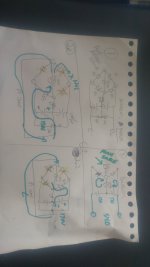
So I would start by re-drawing solution like this

In order -
Upper Left
Lower Left
Lower Right
Upper Right holds equivalent 1st order circuit

I think this will be the solution, and I am guessing that moving around parts on upper right circuit will end up looking like an example somewhere.

Omitted the 60ohm for now
Was sloppy with 10k's - they dont matter
Assume non-ideal diodes

20180727_092236-1494x2656.jpg

.
.
Ok - 4hrs late leaving for work and I still need to scrub my ass in the shower.
Tonight I will go find a Voltage Doubler circuit that matches for theoretical proof.

... At lunch I will go beg for a couple of good caps we can use to test supply ... maybe not (definitely not) form and fit... but for sure ... enough to show we can dump 600V @ 1.7A and that we positively identified problem with supply.

-methods
 
Then...
We form&Fit caps back into supply
Put butterfly sticker on it
Test carefully - and return the supply to its owner (ChargePoint)

Hours Charged - 0
Parts Charges - $0

Lessons learned ?
Eh... a few... for certain.

-methods

P.S. If you tell someone you can fix something... and you tell them you will fix something... fix it :)
 
Back
Top