Bluetooth 10-15s bms review

ninja007 said:
I have a couple of these, and some of the other BMSs from this company on the way for testing, let me know if you want more information on the boards, I'd be happy to share once they arrive. I'm interested in getting the Bluetooth outputs modified into a more user friendly interface for some packs I am working on.

I put my notes about this BMS here: https://opensourceebikefirmware.bitbucket.io/Smart_BMS_with_bluetooth.html

ninja007, maybe you could take better quality pictures to the board that shows the ICs references?? also pictures to the bluetooth module??
 
Thanks for the info, I will take some better pictures once they arrive, they are on the slow boat from China currently.
 
Hi,
I'm new in this Forum but I just have an issue with the 10-15s BT BMS from BMSbattery.
I bought this BMS via aliexpress as 10s bms and opened the solder Bridge to get a 11s bms. The change in the SW was easy.
After that I did the "calibration" of each cell. Unfortunately I made a bridge with my measuring tip and the wires to cell 10 and 11 smoked up.

After the repair of the cell wires cell No. 11 will not be balanced. What may be damaged? - The FET that switches the 100R load resistor, the TI BMS chip (I think not because the voltages of each cell is measured correctly), the diode ... btw. the PCB does not look like barbecued.

Has anyone of you the schema of that BMS and a BOM of the parts between TI BQ76940 and the battery?

Thanks and Regards
troebi
 
troebi said:
After the repair of the cell wires cell No. 11 will not be balanced. What may be damaged? - The FET that switches the 100R load resistor, the TI BMS chip (I think not because the voltages of each cell is measured correctly), the diode ... btw. the PCB does not look like barbecued.

Has anyone of you the schema of that BMS and a BOM of the parts between TI BQ76940 and the battery?
No one has the schematic. Maybe you could start it and help everyone.

Found another good source and for a good price: https://bmsbattery.com/bmspcm/833-smart-bms-10s13s-60a-with-blue-tooth-android-or-ios-app.html
 
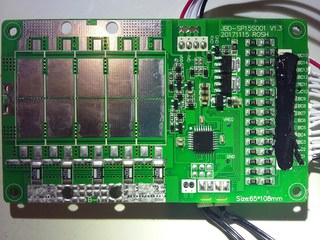
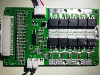
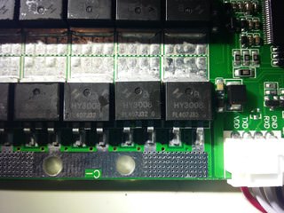
I recently received one of these BMSs and of course the first thing I did was take it apart. Here are some photos I took.


My version was 13S 30A. FETs are HY3008P. B- to C- resistance should be 6.6mΩ / 5 * 2 = 2.64mΩ for the fets + 4mΩ / 5 = 0.8mΩ for the "shunt" resistors for a total of 3.44mΩ. Just like the other ones in this thread it is based of the ATmega328P and BQ76940.
 
flangefrog said:
I recently received one of these BMSs and of course the first thing I did was take it apart. Here are some photos I took.

My version was 13S 30A. FETs are HY3008P. B- to C- resistance should be 6.6mΩ / 5 * 2 = 2.64mΩ for the fets + 4mΩ / 5 = 0.8mΩ for the "shunt" resistors for a total of 3.44mΩ. Just like the other ones in this thread it is based of the ATmega328P and BQ76940.
Thank you for sharing!! Really great images!! With that quality, we could even make the schematic...
 
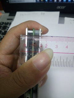
Just a note, the 30A model only comes with an aluminium "heatsink" plate on one side of the PCB. I think the 60A model and probably the 40A model have one on both sides.

I'd recommend the ON Semiconductor/Fairchild FDB86363-F085 as a good replacement FET in the same D2Pak package with 2.0mΩ typical RDS(on). Even better but more expensive is the FDB86360-F085 at 1.5mΩ. The Infineon IRFS7730TRLPBF is also ok but the FDB86363-F085 is better and only costs a little more.

I haven't looked in the software yet but I hope there's an option to customise the shunt resistor values. Those shunt resistors really should be replaced with proper low ohm current sense resistors for high current and accuracy.

Photo a seller sent me of the 60A model:
 
flangefrog said:
I measured 20mV across the mosfets while putting 17A from C- to P- with 10VGSS. So that works out to just under 6mΩ per mosfet which seems about right.
ok. good to hear. mine got IRFB3607 and i measured a voltage drop of 116mV @13A which equal to about 9mOhm which is quite high. especially compared to those nice 3077 and sub 3mOhm for under 2 bucks per FET.
with 5x 3077 in parallel that would be 0.6mOhm compared to 1.8mOhm before. so doubling the amps should work fine with 3077.
 
Alan B said:
If the measurement included other resistance aside from the FET it might not represent the FET alone. Also, there will be two FETs in series if this BMS has only in/out ports and does not have a separate charge port.
voltage drop from SOURCE to DRAIN. that should give quite exact results of the internal resistance?! or is there a better way?
what i did: apply 12V to GATE and then attached a 500W resistor to DRAIN, and powered SOURCE with a regulated power supply. measured AMP and VOLTAGE drop just accross the FET's pins.
 
That could provide a good value if it is a true 4 wire connection that only involves the FETs voltage drop. Ideally this would be measured on the die with separate bonding wires, this measurement made externally will include all the resistances of the leads and bond wires. The best we can do is to measure the leads at the point where they enter the FET with a floating meter.

Doubling the current by improving the FETs assumes that all the rest of the path can handle the increase as well. Sometimes these PC board traces are already pretty stressed.
 
Sorry I don't get if somebody was able to reflash the firmware of this BMS.
I also don't understand where the Windows screenshots come from, I only found the Android app.
And finally, is this firmware compatible with this BMS? But where is the original sparkfun BMS? I can't find it.
 
Back
Top