BMS and parallel batteries

Mike_Kelly

10 mW
Joined
Apr 25, 2023
Messages
22
Location
North America
Say we have two identical lion batteries for grins 36v 10s2p. When a charge cycle is started the BMS charges a little, equalizes, charges a little more and equalized until the battery is full.
1, If the batteries are left connected to the charger the input is turned off because the BMS detects the battery is full.
2. If the two batteries are connected in Parallel will the slightly lower voltage battery BMS detect the higher voltage battery as a "charger" or charge source and shutdown the lower voltage battery output because it is as full as it is going to get?
3. IF we add a solar charger into the mix will it always be detected as a charge source and both batteries BMS will shutoff the outputs of the batteries of the solar charger is left connected while the load is being used?
If a battery has a separate charge port how does that work? Does it turn off the output when it detects a voltage on the charge port?

Thanks very much
 
Say we have two identical lion batteries for grins 36v 10s2p. When a charge cycle is started the BMS charges a little, equalizes, charges a little more and equalized until the battery is full.
1, If the batteries are left connected to the charger the input is turned off because the BMS detects the battery is full.
2. If the two batteries are connected in Parallel will the slightly lower voltage battery BMS detect the higher voltage battery as a "charger" or charge source and shutdown the lower voltage battery output because it is as full as it is going to get?

If they are common port BMS, then the charge port of the "off" battery prevents current flow into the battery regardless of discharge port state.

If they are separate Charge & Discharge port BMSs, and the C ports are parallelled, and the D ports are separately paralleled, then regardless of the state of the charge port, current can flow from a higher voltage source back into the discharge port *even if the discharge port is turned off too*, because the switches used are FETs, which are only switches in one direction, and have a parasitic diode that always allows current flow "backwards" thru them even when "off". Thus, BMS with separate C&D ports are not safe to use parallelled on both C & D ports at the same time.


3. IF we add a solar charger into the mix will it always be detected as a charge source and both batteries BMS will shutoff the outputs of the batteries of the solar charger is left connected while the load is being used?

If the solar panel is generating enough power for the MPPT (or other converter) to provide charge voltage and current to the battery's charge port, it would be "seen" as an active charge source. Otherwise, it depends on the MPPT or other converter's design, characteristics and operation as to what would happen, and whether the BMS is common port or separate C & D ports (and thus whether it is paralleled with your load). There's too many possible scenarios to list them all here in a reasonable amount of time.

Whether a BMS turns off the output during charge (or the input during discharge) depends on the specific BMS design, so you would have to test for this with each different BMS to find out what it does in these situations. (it's unlikely there will be documentation defining it, and sales site page info may not be reliable).

If a battery has a separate charge port how does that work? Does it turn off the output when it detects a voltage on the charge port?
If the BMS uses a common port for C & D, then it is safe to use parallelled completely with a second battery also using a common port BMS.

If either BMS uses separate ports for C & D, then to discharge safely you must physically disconnect the C ports from each other, and to charge safely you must physically disconnect the D ports from each other. If you don't, then those ports act as an uncontrollable connection between the two packs allowing current to still flow out of or into a pack even though the BMS has tried to turn it off to protect it's cells.

Whether a BMS turns off the output during charge (or the input during discharge) depends on the specific BMS design, so you would have to test for this with each different BMS to find out what it does in these situations. (it's unlikely there will be documentation defining it, and sales site page info may not be reliable).
 
Thanks. It is frustrating the vendors do not supply circuit diagrams. It is like flying blind.
Thanks for the info I really appreciate it.
Time to get out the multimeter and scope.
Cheers
 
Spec sheet officially lists them as common port, not separate port:
> BMS Cutout Topology
> Common Charge/Disch Port
 
I am not using grin batteries tho.
I purchased a couple of parallel battery MOS switches. They are slick in that they will sense the highest voltage battery and turn off the others until the high voltage battery sags to the level of the others and then turns them all back on. Once a battery sags below the others it is turned off until they equalize again. But one of the units has a separate charge port and I am not sure how that works with multiple batteries and if it cuts all outputs once it senses a charge voltage on the charge port or if is does something similar in charging the lowest one until it matches the others etc. Lots of possibilities and no info of course.
 
I am not using grin batteries tho.
I purchased a couple of parallel battery MOS switches.


Ok, but those things aren't BMSs, so don't have anything to do with the question you posted to start with, and are mentioned nowhere in it. (yet they would affect what happens in your system)

If you really want to know how the system will work, you'll have to do the experiments and see what happens.

Otherwise, if you want accurate info from us about what your system might do, you need to post your *complete* setup, including a wiring diagram of your proposed parts, exactly the way you intend to connect them, *and* links to the manufacturer data pages for each item involved so we can get their specs and operational modes, etc. Anything you leave out, or post differently from what you actually will do, means anything we reply with is irrelevant and probably useless.

Otherwise, all we're doing here is wasting time talking about possible thigns that might happen using incomplete data without knowing even all the parts of the system involved. :(


I am not using grin batteries tho.
I purchased a couple of parallel battery MOS switches. They are slick in that they will sense the highest voltage battery and turn off the others until the high voltage battery sags to the level of the others and then turns them all back on. Once a battery sags below the others it is turned off until they equalize again. But one of the units has a separate charge port and I am not sure how that works with multiple batteries and if it cuts all outputs once it senses a charge voltage on the charge port or if is does something similar in charging the lowest one until it matches the others etc. Lots of possibilities and no info of course.
 
Yeah, battery blenders are connected to the batteries externally, so don't have much to do with the BMS, which is internal to the battery. Personally, I have a battery blender without a charge port:

The way you charge the batteries with it connected is you plug in each battery in to a separate charger. So charger 1 -> battery 1, battery 1 -> blender, charger 2 -> battery 2, battery 2 -> blender, blender -> controller. It doesn't allow charging through the blender, and doesn't even allow regenerative braking either.

This makes sense since it's essentially a MOSFET in front of each battery's discharge port which is turned on and off based on voltage measurements to make sure no current flows into whatever battery is lower voltage.
This sort of controlled MOSFET circuit is often called an "ideal diode" because it behaves like a diode, but without the associated voltage drop and heating you'd get by just putting a diode in front of each battery's discharge port.

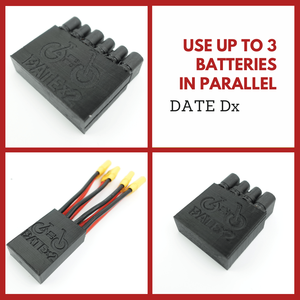
There are battery blenders with charge ports, but you'd have to check the manual/specs for how that is setup and works. For example the DATEx2 works like this:
When charging them through the DATE Dx2C or Dx3C, the opposite will apply, the lower voltage charged battery will be charged first until they will both reach the same voltage and then both will split their charging based on their capacity e.g. ⅓ + ⅔ for 10Ah + 20Ah batteries together or ½ + ½ when the Ah is identical.

Which implies to me there are two separate ideal diode FETs in it. One for charge and one for discharge, with the FET facing a different direction.
 
Last edited:
Thanks very much. I am still at the stage of trying to figure out how to connect all this up. So I don't have any hard and fast design. The reason I was concerned about the BMS is from the perspective of the the two batteries in parallel. Since the BMS is designed to control the charge of the battery I was thinking that when I parallel an external battery I have to consider the effect the external battery has on the BMS of the internal battery. Does the BMS of the internal "see" the external as a charger and therefore cutoff the output of the internal while it is charging, until the voltage comes up. The problem is that none of these vendors, at least in china, has schematics so it is a guessing game. I am concerned that the switch with the separate charge port will cutoff the output while it is charging.
The british company that you found, which is too expensive for me, does not actually say if the batteries being charged are cutoff while charging. It is kinda implied because that is how they work during output.
I have both the switch that you have Inanek and the same company with a separate charge port in the switch. My external batteries are the S002 from these guys and they have a separate charge port.
They have nothing describing how the charge port works.
The bottom line is I have internal battery, external batttery and a solar charger to integrate. Clearly every body plays nice when the switch is used for output controll. But what happens when you throw in the solar panel? I am coming to the conclusion that there is no way and I will have to treat the batteries separately and just charge one off line while I use the other and manually switch them. All this is from the assumption that I would like the solar panel adding energy to mix during riding.
 
I wouldn't do it, but amusingly, it's actually not that rare to plug in a second "range extender" battery's discharge port into the charge port of a first battery. Sometimes with diodes or fuses involved. Lazy people do that when adding a second battery and they don't want to disconnect the first from the controller to put the blender, or even a y-cable in:

Does mean it matters if your BMS is common port or separate port like mentioned above, though. Here's a whole thread of people doing it with a DC-DC converter in-between, which would prevent the first battery charging the second as well and be similar to your solar charger:

Seems kind of pointless, though, for the linked batteries. They have a max charge spec of 2A. My controller uses 30A. So using it for an hour ride would net me an extra 4 minutes? Not worth the extra wiring and complexity to me and the associated decreased reliability and higher chance of thermal problems.
 
Sure but if the ride is 8 hours a day, then that 2amps fill up the battery completely. Also the 2amps represents 72w and at 15w/m we are talking an extra 5 miles.
In case I was not clear I am not proposing connecting the second battery to the charge port of the internal. I am building the bike from scratch so I can connect the internal battery to the switch and the external to the switch the switch to motor. I was assuming if both batteries are "on" via the switch that the BMS sees the ouput but maybe I am wrong? Do internal batteries typically have a separate charge port that goes to the external connector on the frame rather than just "whying" the battery output port to the motor and the external charge connector?
 
Last edited:
I was giving you examples of people charging while riding to illustrate that BMS do not typically disable discharge while charging. For a common port BMS, it isn't even possible for the BMS to distinguish that case, because the charger and the load are wired to the same locations.

If the charger is supplying more power than the controller decides to consume, the BMS current sensor would detect charging. If less, then discharging. The BMS typically has two sets of MOSFETs back to back and enables both, letting them conduct in both directions, since otherwise you'd get voltage drop going across the reverse body diode in one direction of the MOSFETs. Once a p-group is full, and charging current is detected, the MOSFETs facing the right direction to prevent charging are switched off so they become one way instead of two way conductive. Once a p-group is empty, and discharging current is detected, the MOSFETs facing the other direction are turned off to disable discharging.
 
Last edited:
I would not recommend charging lithium with solar, unless it was a very slow rate where there is no situation where the BMS will ever activate. If the BMS ever activates while charging lithium, the solar controller will try to forcibly charge the battery, causing voltage surges which can damage electronics that might be connected to the batteries. If there are more than 2 batteries when 1 bms activates, the second battery will continue to charge until it's bms activates, then the voltage surges will commence. The solar controller will cycle back and forth (voltage surges) until the solar system is shutoff manually.
This occurs due to when the BMS activates it uses Mosfets (instead of mechanical relays) to stop the charge. These Mosfet leak voltage and the solar controller see's a low voltage battery and will continue to try and charge it, even though the battery won't accept a charge.
I do charge 12x 25ah 3s batteries in parallel (each with its on BMS) with solar (365 watt panel) but I have a timer and also an overvoltage protection relay that cuts the charging with a mechanical relay at 12.4 volts. It works for me for the past 2 years and never had any of the BMS activate.
The makeskyblue 60amp mppt controller (which I own) is suppose to prevent voltage surges when used with lithium but have never tested it to see if it actually works. Which ever controller you will use, I would verified (owners manual) to see how it behaves when a BMS activates. Several Mppt and PWM controllers I have used before produce voltage surges with lithium. Makeskyblue is the only controller that states it will prevent voltage surges when used with lithium, havent seen any other controller that makes similar claims.

a make.jpg
 
Back
Top