BMS-controlled contactor for high-amp discharge

harrisonpatm

Moderator
Staff member
Joined
Aug 8, 2022
Messages
1,173
I thought I'd start a new thread split off from this one to discuss DIY BMS contactors at length. Planning stages for my next build.

I'd like to use the salvage contactors I got from Battery Hookup for this one (https://batteryhookup.com/products/te-connectivity-ev200aaana-500a-0-900vdc). Contacts are rated for up to 900v, coil activates at 8-36V, so that's the first issue. For a high-discharge EV, you'll be using a battery pack anywhere from 48-108v nominal. So you'd need to get the voltage down to the coil's rating. Normally I'd use a DC/DC buck converter. But as the BMS is in control of the contactor closing, you don't actually want it running 24/7 with the BMS. So you'd want to put a key switch (ignition? handlebar switch?) in line, in between the BMS and the coil. So how do we get the voltage leaving the BMS down to 12v first, then to the contactor coil? If you were to use a buck converter, you'd still need to have a way to switch the V-in on and off manually, and when you're working with 72-108V packs, that's a big switch, I'd rather switch 12v.

In another thread, I saw someone use a DC/DC converter that operated off a key switch on the input, so that you could work it to not have the converter running 24/7 just to have 12V available to switch on the contactor. That'd be cool, but I'm not sure whether that keyed input is 12V or pack voltage, and I'd rather not switch pack voltage, even at low amps. Has anyone used a specific model of DC/DC buck converter that has a key switch input that can be switch with a relatively cheap switch?

Google has suggested that I use math to find out what resistive load I could place in line with pack voltage and the 12v coil to make it 12v. Or linear voltage regulators is another things I came across. I'm just not familiar with those, maybe someone else is.

I would also want to place the charging leads through the BMS, and not through the contactor. This way I could charge the EV without having to close the contactor. So you would still need a BMS rated high enough to handle your planned max charging current. That shouldn't be a big deal, as charging current is usually not nearly as high as discharge current. Besides, the concept of using a cheap BMS to control a contactor is only good if you have a BMS that's still good enough to monitor series voltages reliably. Therefore, even though this method is a way to not have to use a super expensive BMS, you'll still want a decent and reliable one, and it should be able to handle 20-50amps of charging no problem.

Anyway, up for discussion. I'd love some suggestions on powering a 12v coil off 72v or higher pack voltage, something that I can switch easily. Also, after I gather a few ideas I plan on drawing it up and posting it for other members to use in their projects. Thanks!
 
harrisonpatm said:
I'd like to use the salvage contactors I got from Battery Hookup for this one (https://batteryhookup.com/products/te-connectivity-ev200aaana-500a-0-900vdc). Contacts are rated for up to 900v, coil activates at 8-36V, so that's the first issue. For a high-discharge EV, you'll be using a battery pack anywhere from 48-108v nominal. So you'd need to get the voltage down to the coil's rating. Normally I'd use a DC/DC buck converter. But as the BMS is in control of the contactor closing, you don't actually want it running 24/7 with the BMS. So you'd want to put a key switch (ignition? handlebar switch?) in line, in between the BMS and the coil. So how do we get the voltage leaving the BMS down to 12v first, then to the contactor coil? If you were to use a buck converter, you'd still need to have a way to switch the V-in on and off manually, and when you're working with 72-108V packs, that's a big switch, I'd rather switch 12v.

Since you're only switching a tiny current (whatever the inrush is on the DC-DC at most), you can still use a tiny switch, even with the higher voltage--it should still be rated for the voltage it needs to switch.


However: If the BMS has a switch input that turns it's ports on (assuming all BMS conditions and limits are met at cell level) , then you don't need a switch to turn on the coil or DC-DC. You only need a switch to turn on the BMS. The BMS will then turn on the DC-DC to power the coil. This simplifies everything. ;)


In another thread, I saw someone use a DC/DC converter that operated off a key switch on the input, so that you could work it to not have the converter running 24/7 just to have 12V available to switch on the contactor. That'd be cool, but I'm not sure whether that keyed input is 12V or pack voltage, and I'd rather not switch pack voltage, even at low amps. Has anyone used a specific model of DC/DC buck converter that has a key switch input that can be switch with a relatively cheap switch?
If you're switching the DC-DC input, you're still switching pack voltage; there's no getting around that, unless you have something else already dropping the voltage beforehand...and if you're doing that, you probably don't need the DC-DC. ;)

But cheap controllers do essentially this on their keyswitch/ignition line to the LVPS inside the controller, with a large resistor that, at the current draw of the LVPS, drop enough of the voltage across them to prevent blowing up the LVPS first stage (often an LM317).

So...if the coil can be driven with the output of a linear regulator like the LM317 or similar (there are versions up to a couple of amps, I think, if you properly heatsink them), which brings us to:


Google has suggested that I use math to find out what resistive load I could place in line with pack voltage and the 12v coil to make it 12v. Or linear voltage regulators is another things I came across. I'm just not familiar with those, maybe someone else is.

Doing this like cheap controllers do can work; the big fat resistor dropping voltage to the LM317.The resistor has to be large to dissipate the waste heat created by the current thru it and the voltage across it; the higher the voltage into the system and teh lower the voltage out of it, the more waste heat this will be.

You can even just use the resistor itself, no regulator, if the coil is the only thing driven by it, since it has a wide range of voltage input and the only thing that actually matters is that there is enough current thru the coil to pull and hold the contactor in, but not so much current that it creates too much heat in the coil.


Or you can use just a pure "pass transistor" regulator, whcih is essentially what the LM317 is inside just one component.

Another option for low enough current is the way Justin_LE does it for the input of the Cycle Analyst--it's a pass-transistor type of regulator using a Depletion Mode FET (different from the ones we see in controllers/etc). I'm not familiar enough with those to say how to do it, but there's a schematic of the CA's regulator in my CA Repair thread that may give a start.


I would also want to place the charging leads through the BMS, and not through the contactor. This way I could charge the EV without having to close the contactor. So you would still need a BMS rated high enough to handle your planned max charging current. That shouldn't be a big deal, as charging current is usually not nearly as high as discharge current. Besides, the concept of using a cheap BMS to control a contactor is only good if you have a BMS that's still good enough to monitor series voltages reliably. Therefore, even though this method is a way to not have to use a super expensive BMS, you'll still want a decent and reliable one, and it should be able to handle 20-50amps of charging no problem.
You can use a separate contactor for charging, and still use a cheaper lower current BMS, as long as the BMS has a separate charge and discharge port.

You'd still use the best BMS for the job, just not the version that has to handle the high current via FETs.

Alternately, if you can't get a version of the BMS you want that handles the current you need for charging, you could add FETs in parallel to the existing ones, along with suitable heatsinking, external to the BMS. (I'd rather add a contactor, but the option exists). It's not nearly as complex as adding external FETs to controllers (which requires much more precision in gate timing, bus capacitance, etc, because those are rapidly switched, and these are not.


There are also existing contactor-based BMSs for such purposes (that's where the contactors at batterhookup/etc came from, inside the packs), but because they include the contactor they'd be more expensive. If you can convince a maker of those to sell you a "sample" that doesn't have the contactor included, as an "engineering test project" unit or similar, you can then use your own contactor, especially if the contactors you have are the right coil ratings for the BMS design so you don't need any workarounds.
 
A BMS needs 3.5 to 5 volts to to operated its internal electronic components. Consider where does the BMS get that voltage. Many of the lower end BMSs tap the first 2 or 3 cell strings (or the last 2 or 3). I am gusseting larger units (pure speculation) that have fans and such may also have an an internal buck converter circuit. If the coil power draw is small enough and one can locate that low voltage circuit in the BMS then one might be able to "tap" that for the low voltage source for the contractor.
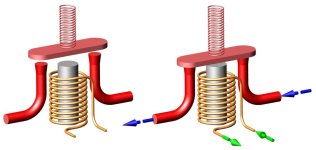
Relay 3D example.jpg
Another more exotic (sophisticated ?) approach is to have a second lower capacity battery pack (say 12 volts) for accessories that is switched on prior to switching on the primary "traction" battery pack. This would be similar to how earlier Hybrdid cars operated with a 12 volt battery for the ICE engine and a separate "traction" battery for the EV motor. Seeing as how there is no ICE engine and alternator one might want a built in charger circuit from the primary to the secondary battery pack.

Consider using something similar to an ICE ignition switch where the accessory circuit and the ignition is energized prior the the starter circuit. In fact think about four separate switch circuits:
1) Accessory at 12 Volts
2) High Voltage Precharge
3) Initial activation of contactor coil circuit
4) Contractor coil "hold" voltage circuit (aka "economizer")

One might even want to consider a small MPU programmed to switch these circuits in the proper sequence and timing. Of course the more sophisticated one's system becomes the more things there are to be maintained and the more things there are to break (to go wrong, go wrong, go wrong ....).

Personally I want to eliminate the parasitic power drain of the BMS as well. Using an separate active string balancer can help but monitoring the over/under voltage, over/under current and/or temperature is more challenging.

Leave us not forget about the back-emf when the contactor is shut-off as well.

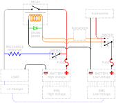
EDIT: Image deleted, see below
 
amberwolf said:
You can even just use the resistor itself, no regulator, if the coil is the only thing driven by it, since it has a wide range of voltage input and the only thing that actually matters is that there is enough current thru the coil to pull and hold the contactor in, but not so much current that it creates too much heat in the coil.


Or you can use just a pure "pass transistor" regulator, whcih is essentially what the LM317 is inside just one component.
I wanted to open the new thread because it's obvious that if you want to DIY it, there's a dozen different directions to go. However, if it were me and my build, I would go with one of the above 2 solutions.

Attracted towards the single resistor issue, I'm glad you also agree that since the coil supposedly operates at a nice wide 9-30vdc, there's not a specific target voltage to hit. "But what about so much waste heat!?!?!?" If it's less than 20 watts, I'll take it. I never run my bike for longer than 1 hour. 20wh is only about 4 hours of charging a phone. Or, like 10 seconds of hard acceleration, lol. The tradeoff is that it'd be one single component, very little to go wrong.

If I went with the singe resistor method, and put a key switch in line, would I essentially be switching the 9-30v? Or would I still be switching 72v or more pack voltage, it's just that the coil only sees 12v or so of it? On my current build I'm switching 0.1A, 72v on a switch that's technically only rated for 12v. I wouldn't want to push it any more than I already have.
 
harrisonpatm said:
If it's less than 20 watts, I'll take it.

I think I posted this in the other thread as well: here is a spec sheet for that particular contactor
https://www.te.com/commerce/DocumentDelivery/DDEController?Action=srchrtrv&DocNm=EV200_R_TBD_KILOVAC_EV200_Ser_Contactors&DocType=CS&DocLang=English

According to that: "Holding Current (Avg.) 0.13A@12V, 0.07A@24V" (or 1.5 to 1.7 watts)

harrisonpatm said:
If I went with the singe resistor method, and put a key switch in line, would I essentially be switching the 9-30v? Or would I still be switching 72v or more pack voltage, ...
Put the switch ahead of the inline dropping resistor and the switch will see the full 72 volts.
Put the inline dropping resistor ahead of the switch and the switch will see 12 volts.
In either case the switch will still switch the full current load of the circuit (as will the contactor coil).

I think it would be preferable to use a Dropping Resistor plus a Voltage regulator. You are going to have waste heat of the resistor in either case but with a regulator the coil and the switch will only have to deal with the current needed by the coil.
 
LewTwo said:
harrisonpatm said:
If it's less than 20 watts, I'll take it.

I think I posted this in the other thread as well: here is a spec sheet for that particular contactor
https://www.te.com/commerce/DocumentDelivery/DDEController?Action=srchrtrv&DocNm=EV200_R_TBD_KILOVAC_EV200_Ser_Contactors&DocType=CS&DocLang=English

According to that: "Holding Current (Avg.) 0.13A@12V, 0.07A@24V" (or 1.5 to 1.7 watts)

harrisonpatm said:
If I went with the singe resistor method, and put a key switch in line, would I essentially be switching the 9-30v? Or would I still be switching 72v or more pack voltage, ...
Put the switch ahead of the inline dropping resistor and the switch will see the full 72 volts.
Put the inline dropping resistor ahead of the switch and the switch will see 12 volts.
In either case the switch will still switch the full current load of the circuit (as will the contactor coil).

So the contactor coil is going to see the 1.5 to 1.7 watts, as well as the load drawn by the resistor?

As for the switch advice, thank you for the placement advice. Should be fine to handle the current in either case, just want to make sure if I get a cheapo 12v handlebar switch, I only want it to see 12v.
 
Alright, assuming 96v pack voltage, I want to put a series resistor in with the coil so that the coil only sees 12v. Coil draws 0.13A at 12v, according to the datasheet.

I found a voltage calculator online that suggests I should use 650 ohms of resistance to bring 96v down to 12 at that amperage. Anyone want to check my math on that?
 
harrisonpatm said:
Attracted towards the single resistor issue, I'm glad you also agree that since the coil supposedly operates at a nice wide 9-30vdc, there's not a specific target voltage to hit. "But what about so much waste heat!?!?!?" If it's less than 20 watts, I'll take it. I never run my bike for longer than 1 hour. 20wh is only about 4 hours of charging a phone. Or, like 10 seconds of hard acceleration, lol. The tradeoff is that it'd be one single component, very little to go wrong.


If I went with the singe resistor method, and put a key switch in line, would I essentially be switching the 9-30v? Or would I still be switching 72v or more pack voltage, it's just that the coil only sees 12v or so of it? On my current build I'm switching 0.1A, 72v on a switch that's technically only rated for 12v. I wouldn't want to push it any more than I already have.

If the key switch is in series with the resistor and coil and battery voltage, then when it's open circuit the entire voltage is across the switch. If the switch is only rated for 12v, it means the gap it creates when open is only guaranteed to be enough to block 12v, though it generaly is enough to block quite a lot more. If the switch is a tiny one it's not expected to break much of an arc as there shouldn't be much current flowing thru it; it's likely it will work fine at a few times that voltage, but there isn't a guarantee. Normally the time a problem happens is when opening an under-rated switch: arcing can occur from current flow and weld the contacts together. At very low currents this is unlikely. Over time spark damage could wear the contacts out, but it generally takes a lot of cycles to do that.

When the switch closes, it now sees zero volts (or whatever it's resistance creates across it at whatever current is flowing, basicaly zero for this purpose).


EDIT: The math below is wrong; I used the wrong formula to derive resistance (swapped voltage and current :oops: ). Working it out in a subsequent post leaving this one intact to show how *not* to do it :

The voltage is now across the resistor and coil. If the coil current spec is
"Holding Current (Avg.) 0.13A@12V, 0.07A@24V"
then other than the initial inrush current for a moment as the coil field builds, for 36v the guesstimated current would be about 0.13A / 3 = around 0.05A, or 50mA. Might be a bit more or less; the less current you can get away with and still ensure holding it closed under vibration, the better (less wasted power). If you have lab PSU with adjustable current and voltage, you can set it to 36v and 0A, then up the current very slowly until the contactor closes, and see what it is. Tap the contactor in differnet ways to simulate vibration to ensure it won't open or chatter at the coil current it's set to, and if you like drop the current until it does open or chatter and then raise it till it doesn't.

So...let's just assume it's 50mA, and you want 36v across the coil, and 72v - 36v means there's 36v left to absorb across the resistor. So 50mA / 36v = 0.0013888888888889 ohms. call it 1.4 milliohms. (it has to be very low because the coil resistance is very low, so you are basically providing a resistance equal to the coil's to drop half the voltage in the circuit).

The resistor must be able to dissipate the heat, so the power wasted in it will be 36v x 50mA, or 1.8W, the same as the contactor coil. So you don't need a huge resistor for this purpose, like you would in a higher-resistance circuit like a linear regulator. I poked around real quick with google (rather than a component selector at mouser/digikey/etc) and found 1.4mohm resistors in more than 1W hard to locate, but you could use two 1W (or higher) 3milliohm resistors in parallel. There are quite a few of those, like this
https://www.mouser.com/c/passive-components/resistors/current-sense-resistors/current-sense-resistors-smd/?power%20rating=3%20W&resistance=3%20mOhms
and that gives you 1.5milliohms, whcih does drop the voltage across the coil a bit, but will probably still work. If you use an SMD shunt it might be made to need to be mounted to PCB (or something else) to shed the heat, but if you're using two 3W in parallel, it shouldn't be a problem because there's now 6W of heat dissipation ability and you only need a third of that.


The total wasted power is the total circuit current and the total circuit voltage, which is 72v x 50mA, or about 3.6W.


You can use the same math to determine everything for other pack voltages.


One thing to consider is that the pack voltage will be higher at full charge and lower at empty. The different voltage thru the same resistance will cause different current flow. As long as that is still enough at lowest voltage to hold the contactor closed, and at highest voltage not more current than the coil can take, you're set.


That's what math says. Now you just have to experiment to make sure I have a clue to what I'm doing. :lol:
 
amberwolf said:
So...let's just assume it's 50mA, and you want 36v across the coil, and 72v - 36v means there's 36v left to absorb across the resistor. So 50mA / 36v = 0.0013888888888889 ohms. call it 1.4 milliohms. (it has to be very low because the coil resistance is very low, so you are basically providing a resistance equal to the coil's to drop half the voltage in the circuit).
See, this is why I have people on the internet check my math. I must have been doing it in the wrong direction to get 650ohms. But I follow your math, so I'll go with that. Mind you, I haven't actually started this build yet, so I won't be able to test it for awhile, but its a good start.

amberwolf said:
The resistor must be able to dissipate the heat, so the power wasted in it will be 36v x 50mA, or 1.8W, the same as the contactor coil. So you don't need a huge resistor for this purpose, like you would in a higher-resistance circuit like a linear regulator. I poked around real quick with google (rather than a component selector at mouser/digikey/etc) and found 1.4mohm resistors in more than 1W hard to locate, but you could use two 1W (or higher) 3milliohm resistors in parallel. There are quite a few of those, like this
https://www.mouser.com/c/passive-components/resistors/current-sense-resistors/current-sense-resistors-smd/?power%20rating=3%20W&resistance=3%20mOhms
and that gives you 1.5milliohms, whcih does drop the voltage across the coil a bit, but will probably still work.
If the datasheet is to be trusted, that's why it might be nice to use the aforementioned contactor, with it's wide voltage activation range.

amberwolf said:
The total wasted power is the total circuit current and the total circuit voltage, which is 72v x 50mA, or about 3.6W.
Dude, I would love for your math to be right on this. 3.6w? Off a 5-10kwh battery? So easy. Very worth the stability and reliability of a simple resistor, nothing to break or fail.
amberwolf said:
One thing to consider is that the pack voltage will be higher at full charge and lower at empty. The different voltage thru the same resistance will cause different current flow. As long as that is still enough at lowest voltage to hold the contactor closed, and at highest voltage not more current than the coil can take, you're set.
Worth testing, but again, the wide voltage range on the contactor should be a nice buffer for it.


amberwolf said:
That's what math says. Now you just have to experiment to make sure I have a clue to what I'm doing. :lol:
I ask because you know more than me
 
harrisonpatm said:
See, this is why I have people on the internet check my math. I must have been doing it in the wrong direction to get 650ohms. But I follow your math, so I'll go with that.
No, I used the wrong formula...so my post is wrong. But I'm typing up a subsequent post with the *right* math. :oops:
 
amberwolf said:
harrisonpatm said:
See, this is why I have people on the internet check my math. I must have been doing it in the wrong direction to get 650ohms. But I follow your math, so I'll go with that.
No, I used the wrong formula...so my post is wrong. But I'm typing up a subsequent post with the *right* math. :oops:

Ah geez, too late, blew myself up already from listening to strangers on the internet!
 
harrisonpatm said:
Alright, assuming 96v pack voltage, I want to put a series resistor in with the coil so that the coil only sees 12v. Coil draws 0.13A at 12v, according to the datasheet.

I found a voltage calculator online that suggests I should use 650 ohms of resistance to bring 96v down to 12 at that amperage. Anyone want to check my math on that?
Hmm. that result makes me doubt myself now. My math above must be wrong...so I'll work out the math again here for the new voltages.

So...assuming I am remembering ohms law correctly via my modernized version of the ancient and politically incorrect saying:

The Vulture sees the Coyote next to the Rock (V = C x R); the Coyote sees the Vulture *over* the Rock (C = V / R), and the Rock sees the Vulture over the Coyote (R = V / C).

So...I messed up in the above post and got the last equation backwards somehow. :oops: That completely screws up the math and all the derived numbers there. :(

Thus:

96v - 12v across the coil means 74v leftover to drop across the resistor.

To create 130mA current (current is the same everywhere in the circuit) at 74v, R = V / C or 74 / 0.13 = 569.2307692307692 ohms, or about 570 ohms. it's proportionally greater than the coil resistance to get the appropriate ratio of voltage.

To verify this, and get coil resistance from scratch instead of inheriting it from the other post, that's 12v at 130mA, so we need R, so thats' R = V / C, or 12 / 0.13 = 92 ohms.

570 / 92 = 6.195652173913043 or about 6.2 : 1 ratio between resistor and coil. 6.2 * 12v = 74.4, so with all the rounding up we're in the ballpark, so the math in *this* post should be correct. :lol: :oops:


So then power is still Watts = Volts x Amps so the 12v coil at 0.13A gives 1.56W of power, in ballpark so good. :)

Dropping resistor is 74v x 0.13A = 9.62W, and looks about 6x the coil power, so that's good too.

Total power loss in the circuit is then about 11-12W.


So the minimum resistor you would need to get is a 10W (or more) 570ohm resistor. That's a lot bigger than the previous calculations because of my mistake in those... 10W is pretty close to the actual usage, so you might want a bigger one if there isn't good airflow where it will be located.

A very quick poke at Mouser via google finds this part
https://www.mouser.com/ProductDetail/Ohmite/80F562?qs=WXkWFdy7yGk7JAHhkvBl1A%3D%3D
that is 520ohm. That puts more current thru the system, and a higher proportion of voltage across the coil, by the ratio of 570/520. But you could use a 50ohm 10W in series with it to get the full 570ohms. They probably have plenty of other parts suitable, but I did not use their configurator to find any others. :)

Its' not really small, at 46.8mm x 10.3mm (1.84" x 0.4", or roughly pinky-sized).

And it will be hot, probably to hot to touch (probably hot enough to melt plastic next to it, etc). A quick google on various resistor datasheets shows temperatures in the neighborhood of 200C at full 10W power dissipation.

Using a bigger (higher wattage) resistor doesn't really change how hot it gets, but it makes it less likely to have a problem because of the heat.


Anyway, all the formulas are out there (pretty much just ohm's law, and a ratio of the votlage you want on the coil vs the total voltage of the supply), so you can check my math to make sure before buying stuff. :oops:
 
harrisonpatm said:
If the datasheet is to be trusted, that's why it might be nice to use the aforementioned contactor, with it's wide voltage activation range.
I expect the contactor datasheet is trustworthy.

Dude, I would love for your math to be right on this. 3.6w? Off a 5-10kwh battery? So easy. Very worth the stability and reliability of a simple resistor, nothing to break or fail.
Well, even with the "right" math it looks like it's only a dozen watts or so total.
 
Still less than my hypothetical threshold of 20w. Still, I opened the thread for other ideas, there's plenty more to explore, for people who don't want to waste a dozen watts. And hey, it means my first guess at 650ohm resistor wasn't too far off!

I never had heard the politically incorrect version before, gave me a good laugh.
 
Thoughts:
Thanks to AmberWolf for running through the math. One thing that should be mentioned is that sometimes one will use two resistors of twice the resistance value in parallel because they do not happen to have the correct resistor at hand. However it also means that only half the current is running through each resistor and the resistors can be physically separated to spread the heat dissipation over a larger area.

I have several electromagnetic relays in hand as well as the two from Battery Hookup on order. I roughly divide them into two types:
1) Single Voltage (The contactor circuit and the coil circuit both operate at the same voltage)
2) Multiple Voltage (The contactor circuit and the coil circuit operate at the different voltages)

The problem as I see it is the lack of convenient high-voltage/low-current switches for the coil circuit. There are a few 48 Volt DC rated switches but darn few over that (those that do exist tend to be both bulky and expensive). That makes "Multiple Voltage" relays an attractive option for E-Bikes particularly as battery pack voltage increases.

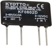
This thread was an offshoot from a thread one I started about SSRs (Solid State Relays). In that thread I used the example of a "Hockey Puck" style SSR. However SSRs also come in the SIP (Single Inline Package) form factor like this one on Amazon:
https://www.amazon.com/dp/B00B888WVC
SSR-SIP.jpg
Datasheet: https://www.jameco.com/Jameco/Products/ProdDS/172591-Revised.pdf

Note the high voltage side of this SSR has a an extremely wide range of 3 to 60 Volts DC. One of these can be used with a "Single Voltage" electromagnetic relay to produce a "Hybrid Multiple Voltage" relay. Or they can be used with a "Multiple Voltage" if one just needs to expand the voltage range of the coil (i.e. if one wants to control it from a 5 Volt MPU). It also has the advantage of totally opto-isolating the High and Low Voltage circuits. There are similar units up to 200 Volts DC output (OPTO ODC15A). They cost less than $10 .... which means that one of these and a cheap 12 Volt DC switch is likely less expensive than a equivalent high voltage switch.

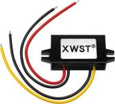
That of course still leaves the problem of sourcing the Low Voltage. For a bench charger/test I would likely just use a wall wart. However I think for many E-Biker DIY builds that a PWM or Buck 12 Volt DC converter is likely a practical solution. They are available in a range from 0.5 to 15 amps depending what other Low Voltage equipment one might have planned for their build. They are relatively simple to install, inexpensive and easily replaced. Example:
https://www.amazon.com/dp/B0B5KPXBGW/
XWST 12Volt 1 Amp(small).jpg
 
LewTwo said:
The problem as I see it is the lack of convenient high-voltage/low-current switches for the coil circuit. There are a few 48 Volt DC rated switches but darn few over that (those that do exist tend to be both bulky and expensive).

If it helps, here's a Mouser list of just SPST toggle switches that handle over 80VDC, in any current rating or other parameters (except all are non-illuminated; they may have some that lightup too, didn't check). (can be narrowed down or broadened more, or change to other switch types)
https://www.mouser.com/c/electromechanical/switches/toggle-switches/?contact%20form=SPST&illuminated=Non-Illuminated&voltage%20rating%20dc=80%20VDC%7C~125%20VDC%2C%20250%20VDC%7C~250%20VDC

They definitely aren't cheap for most of them, but there are a couple that are, but are only available in bulk quantities. :(
 
amberwolf said:
LewTwo said:
The problem as I see it is the lack of convenient high-voltage/low-current switches for the coil circuit. There are a few 48 Volt DC rated switches but darn few over that (those that do exist tend to be both bulky and expensive).

If it helps, here's a Mouser list of just SPST toggle switches that handle over 80VDC, in any current rating or other parameters (except all are non-illuminated; they may have some that lightup too, didn't check). (can be narrowed down or broadened more, or change to other switch types)
https://www.mouser.com/c/electromechanical/switches/toggle-switches/?contact%20form=SPST&illuminated=Non-Illuminated&voltage%20rating%20dc=80%20VDC%7C~125%20VDC%2C%20250%20VDC%7C~250%20VDC

They definitely aren't cheap for most of them, but there are a couple that are, but are only available in bulk quantities. :(
I actually have a couple of the Carling Tech toggle switchs (which are reasonably priced) however they are somewhat bulky.
https://www.mouser.com/datasheet/2/65/DK_EK_Series_Details__26_COS_0-1776091.pdf
 
LewTwo said:
amberwolf said:
LewTwo said:
The problem as I see it is the lack of convenient high-voltage/low-current switches for the coil circuit. There are a few 48 Volt DC rated switches but darn few over that (those that do exist tend to be both bulky and expensive).

If it helps, here's a Mouser list of just SPST toggle switches that handle over 80VDC, in any current rating or other parameters (except all are non-illuminated; they may have some that lightup too, didn't check). (can be narrowed down or broadened more, or change to other switch types)
https://www.mouser.com/c/electromechanical/switches/toggle-switches/?contact%20form=SPST&illuminated=Non-Illuminated&voltage%20rating%20dc=80%20VDC%7C~125%20VDC%2C%20250%20VDC%7C~250%20VDC

They definitely aren't cheap for most of them, but there are a couple that are, but are only available in bulk quantities. :(
I actually have a couple of the Carling Tech toggle switchs (which are reasonably priced) however they are somewhat bulky.
https://www.mouser.com/datasheet/2/65/DK_EK_Series_Details__26_COS_0-1776091.pdf
Yeah, if they get too bulky, starts to become easier to just get one of those cheaper battery disconnect switches that can handle a ton of current and voltage.

Especially when you get into higher power builds at 96-108 nominal volts
 
harrisonpatm said:
I'd like to use the salvage contactors I got from Battery Hookup for this one (https://batteryhookup.com/products/te-connectivity-ev200aaana-500a-0-900vdc)

This won’t help you now as you already got the contactor but for future builds it might be good to know that the LEV200 contactors have a few different coils, i currently run one in my efoil through the BMS at 12s battery voltage. If bms trips then coil circuit is opened and contactor breaks the main circuit.
 
Thank you, that's good to know in the future. I just couldn't pass up on the great deal for the $30 contactors. Besides, I wanted to open the thread for this concept as a whole, so your advice will help someone else looking up this idea for their build.
 
I havent seen this thread before, but this might be interesting:
https://www.aliexpress.com/item/1005004139484587.html?pdp_npi=2%40dis%21SEK%21SEK%20520.66%21SEK%20520.66%21%21%21%21%21%402101d91e16655955989058862e9aeb%2112000028161713714%21sh01&spm=a2g0o.store_pc_home.productList_2002531203100.pic_0
Only seems to be available for up to 24s, but as this is in the ebike section I guess it is mote than enough :wink:
 
j bjork said:
I havent seen this thread before, but this might be interesting:
https://www.aliexpress.com/item/1005004139484587.html?pdp_npi=2%40dis%21SEK%21SEK%20520.66%21SEK%20520.66%21%21%21%21%21%402101d91e16655955989058862e9aeb%2112000028161713714%21sh01&spm=a2g0o.store_pc_home.productList_2002531203100.pic_0
Only seems to be available for up to 24s, but as this is in the ebike section I guess it is mote than enough :wink:

NIce, thanks. I'd personally still like a 30s version, but its good to know this is available. Anybody use this particular model before?
 
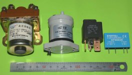
Just to give some relative size perspective:
Relays(1280).jpg
Going from Left to Right:
1) 60 Volt, 150 Amp Golf Cart relay sold by ElectricScooterParts.com
2) Savaged "TE Connectivity 12v 135a 0-450vdc Tyco" sold by Battery Hookup
3) 48 Volt 80 Amp "Bosh" style automotive relay sold by ElectricScooterParts.com
4) Kyotto low power SSR

Note that while ElectricScooterParts.com "claims" the Bosh style relay is good for continuous duty, the manufacturer has it listed for intermittent duty. The only Bosh style relay I was able to find actually rated for continuous duty was rated at 10 Amps. It is interesting to note that it is really not much smaller than the contactor from Battery Hookup.
 
Something to note about at least some contactors is that they are internally evacuated of air, to help lessen creation of plasma during arcing on turn on / off events, to minimize the arcing itself and the damage to the contacts. Some may use a nitrogen fill.
 
Back
Top