BMS facts and how to charge lifepo4 without it!

Me too i run my pack without a bms... but it dosent mean that i don t believe in a bms or that i would not add later on 2 of the 8 cells monitoring from hobbyking with audible alalrm and the software for the computer.

but the fact is that if a cell dies and the pack was protected by bms ...they say you just change the cell

but if you have no bms and a cell dies, they think the pack is good for garbage. it s the same solution in the end.

and if it happens too many times maybe that owner should think learning more about lifepo4 or get a good bms or get out of battery powered vehicule. loll
 
I have a 16S3P A123 pack with no BMS (built as (4) 4S3P). I put all cells in parallel before building my packs for a couple of days on a single cell charger. I now charge them with a 5amp / 12 volt SLA smart charger by putting the (4) 4S3P in parallel (Anderson connectors). During use, I montor my CA and never draw more then 6 AH from a fully charged pack. So far (~20 cycles) they are staying in balance. That said, I intend to get the new goodman BMS when availble or maybe the cellog.
 
And by the way i ran all last summer with only one incident where i ran the bike after two weeks without use and did not charge before use ( wich i will now do ) and noticed that it was not behaving the same (only by looking at cycle analyst) and luckuly by the end i had a flat and had to walk home and one of the cell was 2.5 volts so i recycled a couple of times and it is now back to normal, i guess i found the weak cell that way ... i now check this one the first.
 
morph999 said:
if you are running your pack to 50 - 60 % DOD and you kill a cell, that cell wasn't any good anyway. That's how I look at it. Suppose you take your pack out fully charged, you run it to 50 - 60 % and when you get back, you discover that a cell is dead. How would a monitor help you at all in that situation assuming you are running prismatic cells? It wouldn't help you at all. YOu'd only find out a little sooner.

The problem here is you're limiting your 'logic' to a single event - a bad cell. What happens when a connection loosens a bit and a cell or a couple of cells don't fully charge? Or maybe one cell has a bit higher resistance when cold and doesn't take a charge a quickly as the other cells? There are a LOT of reasons why cells can get out of balance or not be completely charged when the charger shuts down. And that completey ignores the days when you only need to take a short ride to the post office so you pull the pack off the charger before it's done.

Over-discharging a cell - regardless of the reason - kills the cell. Catching a low cell before it's discharged to zero or reversed keeps the cell alive and saves the time and money it takes to diagnose and swap cells. Anyone that thinks they can prevent over discharge by only using 60% capacity is only looking at part of the 'problem'. They're likely thinking along the lines of: "The only way I'll have a low cell is if it's already bad - and at that point I don't care if it completely discharges." But they're missing the rest of the story: "But maybe the low cell isn't bad - instead of guaranteeing it's death, maybe I can find out why it's not fully charged, fix the problem, and get more than 20 cycles from the pack."

Here's a real-world example of what I'm talking about. This is a fully-charged 21S pack on a cold-weather ride - with and without the 2.7V LVC connected. The blue line is 3.0V, the red line three 'ticks' below is 2.7V. The LVC, connected to the throttle, limited the max current I could draw from the pack and limited top speed. But it kept the low cells from being overdischarged. Keep in mind - this is the FIRST 10 MINUTES from a fully-charged pack.

View attachment wihout_LVC.jpg


Simply measuring the cell voltage once a quarter will not show what the pack is doing. Yes - one can use single cell chargers to tweak the low cells after the bank charger finishes. And yes - if one has matched the cells, always rides at the same temperature on the same route at the same throttle setting, they might feel that's enough risk management - especially if they consider their time to be worthless and their pack disposable... But as you can see above - cells change as they age and the four lower-performing cells are working harder than the rest even fresh from a full charge.

Andy
 
Andy, on the 2nd graph, does that mean every 5 minutes or so the LVC was kicking in? What kind of enjoyable ride would that be anyway? You'd have to replace that cell eventually with or without LVC.
 
i just want to say im not suggesting not to use a bms,as i have every intention of installing one,im just saying that if a bms stops working properly the possibility exists to keep on charging by other means.
 

You bring up several very good points however, as most that don't use a BMS have stated they verify the charge before riding. So a bad connection for example would have been noticed by low voltage during this verification. As to our time...everyone has there own value on their time. When I was working for a living it was very expensive. But now that i am retired and I am doing this 100% for my personal enjoyment it's not worth a hell of a lot. That being said my money still is.

My question to you is this; your graph indicates a LV condition on several ocations. And you say that it only limited your max speed. But it has always been my understanding ( and no one here has ever indicted it was wrong) the if a low voltage accured it BMS would shutdown the pack discharge. This is not the same as limiting your speed. Are you saying that after the BMS shutdown you reset it and continued on at a reduced speed because of the LV condition? Or did the BMS actually limit your max speed automaticly? To me LVC means "low voltage cutoff" not "low voltage control" But If a BMS only linits your current draw it is a different situation and i would like to hear more and where you bought this BMS.
 
morph999 said:
Andy, on the 2nd graph, does that mean every 5 minutes or so the LVC was kicking in? What kind of enjoyable ride would that be anyway? You'd have to replace that cell eventually with or without LVC.

The entire graph is only 10 minutes - and the horizontal voltages for the first ~2 minutes is putting on a helmet and backing the bike out of the garage.

No. The LVC signal is connected to the throttle input. It's not 'jerky' like a controller LVC or an LVC connected to the brake inhibit. It behaves as if the BMS limits how far open you can move the throttle - it's very smooth. I actually prefer the jerkiness of the brake inhibit as it tells me that something's happening. The only thing I can 'sense' with the throttle connected LVC is that I might have lost some top speed.

Enjoyment is subjective, but I'm much more relaxed knowing that I can ride and not constantly stare at the PakTrakr display. A low cell can drop too far so fast that it's not a comfortable ride for me at all.
 
dumbass said:
My question to you is this; your graph indicates a LV condition on several ocations. And you say that it only limited your max speed. But it has always been my understanding ( and no one here has ever indicted it was wrong) the if a low voltage accured it BMS would shutdown the pack discharge. This is not the same as limiting your speed. Are you saying that after the BMS shutdown you reset it and continued on at a reduced speed because of the LV condition? Or did the BMS actually limit your max speed automaticly? To me LVC means "low voltage cutoff" not "low voltage control" But If a BMS only linits your current draw it is a different situation and i would like to hear more and where you bought this BMS.

How the operator 'feels' the LVC event depends on the type of LVC signal and how it's used. For example - in the E-S/Goodrum/Fechter BMS, the low voltage event 'detection and reporting system' is based on a voltage detector that signals when a cell hits the low point. The 2.1V detector will signal as voltage drops down thru 2.1V, and will release it's signal when voltage rises above 2.2V. There's no latching at all, just the .1V difference between 'signal on' and 'signal off'. Since nothing latches off, there's nothing to reset. Protection is automatic, repeatable, and much faster than one can respond to a LED or a buzzer.

Let's use the low voltage signal to do something.

One method is to connect it to the controller's brake inhibit line - just like another brake lever.

View attachment LVC_Brake.jpg

When a cell drops thru 2.1V, the BMS essentially closes a brake switch. This tells the controller to cut power to the motor. Once there's no load on the pack, cell voltage recovers. Once the low cell voltage springs back up thru 2.2V, the virtual brake handle is released and power is restored. If the throttle is left open thru multiple low voltage events, the rider will feel about 1-4 pulses per second depending on how quickly the cell voltage recovers.

Another method is to use the low voltage signal to operate a relay or contactor or MOSFET switch that cuts power from the pack. One of Gary Goodrum's LVC boards has such an active power disconnect function. Same scenario here as well - cell drops low, active shut-off opens the wire to the controller, cell voltage recovers, power is restored. I don't know how quickly the pulses will happen here - I haven't ridden this type of disconnect.

The method I'm trying on my bike - and the method that was in use when I collected the charted data - is a throttle pull-down. The circuit is listed in one of the BMS threads.
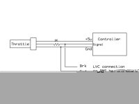
Throttle_Tie_in_for_LVC.jpg

From looking at the circuit, I expected that a low voltage event would abruptly cut the throttle and result in feeling 'power pulses'. But with my hall-effect throttle there's no jerking at all - just what seems to be a reduction in how much current I can draw. With no LVC connected, I can twist the throttle and pull 100A regardless of the status of the pack. With the LVC signal connected to the throttle, I was limited to about 73A max as a cell bounced around the 2.7V set point. It was very smooth and was undetectable on the road except that it seemd my top speed was down a bit and that acceleration dropped off a bit faster than normal. I didn't realize I had bounced off LVC until I looked at the data after the ride.

I hope that helps some,
Andy
 
This is all interesting as we were doing this before the posting of this information here.
It is great to see others with the same mindset.

There are several ways to accomplish the monitoring of the charge and discharge of your batteries. This one posted by maxwell65 is just another way of doing it. It seems to work well if you know what you are doing.

If there were quality BMS units that were inexpensive and really did their job, most of us would never have considered this way of running our Batteries.

******* Our setup******
I have 8 single cell chargers all tied to a 8s4p box through a Molex which I just plug in to start the charging process.

No BMS and since they are isolated chargers, you can charge the box all at one time.

They charge up better than when I had the POS BMS in the system. I have received better BMS units since then (Replacement units) but am content with how everything is running. The chargers are only 14$ a piece delivered and I can see if I have any issues by how long it takes for all the red lights to go green.

Since I have 4 Headway cells paralleled together and then set up as groups of eight, the 4 paralleled cells cannot really be monitored individually anyway. I use the controller to limit the LVC and set the point high enough before most damage should occur even if I have a crappy cell. I do not need to run my bike to 80%.

We just did the changover recently. I should have some really good updated distance numbers as soon as it WARMS UP!!! :):)

Juiced
 
Yeah, but your application is the exception not the norm.....your single cell chargers are probably only 2 amp output units? Take forever to charge a 50-60ah pack. We want to charge in 4-5 hours and run to 80% DOC. Andys graphs cleary show that that 2.1 volts can come pretty fast based on low temperature and/or lower state of charge. The goodman bms with cell level LVC and HVC (call it balance if you like) with modulated charger seems the way to go. I tried a couple of volt blockers a while back...and yes they started to bleed current at 3.6 volts.... but without charger modulation the cell kept right on charging!
 
pgt400 said:
Yeah, but your application is the exception not the norm.....your single cell chargers are probably only 2 amp output units?

Absolutely! (40 AH)

Although I have not really seen any "Normal" bikes to date. All of them have their different designs and particular purpose.

I can ride it to work (9 Miles one way), go to lunch, run to the parts store and ride home. I can charge it overnight.

I am working on a solar charging station now as well.

If I wanted to charger it faster, I would just get bigger chargers! :) :)

Battery Management Systems have their place.
This particular setup works well for me. When the BMS company get their act together and build one that will work well ( and fit in the allotted space) on my motorcycle I will add it, until then this works fine.

Juiced
 
I use two chargers. That way, I'm positive that I at least put some kind of electricity into the pack. I can use a 10 amp charge for 1 hour or 30 min then finish it up with the 3 small chargers that I have.
 
Andy,

An absolutely great explanation on how it works. Thanks, I really learned a lot from it. Your comments about what I will call pulsed motor response is the same comment that was stated by Jim Olson from Cyclone USA the first time he tried a lifepo4 pack with a 500w Cyclone kit. Ether the pulsed protection or the speed limiting protection sounds like something I would consider. Now that you have done such a great job explaining the discharge protection can you please explain the charging protection? From what I have read (and this is something I don't like) is that the BMS is just bleeding off the voltage on high cells. I have also read that with some BMS they cut off the charge once the first cell reaches a full charge.

You mention “Gary Goodrum's LVC boards”. Is this only a LVC or a BMS with LVC with ether pulses or a reduction is current draw. I like the idea of using individual cell chargers but would like the addition of a low voltage control.
 
Just as a side note.

I removed the cells today from one of my BMS (not a great BMS unit ) boxes that I fully charged yesterday.
I did a load test on them and was surprised on how low in power they were. I re-charged them using the 2 amp LifePo4 charger
and it took forever to top them off.

I waited until this evening and then did a load test. The batteries now ran as I would have expected.

I will be using the individual chargers until I see and proven BMS that can match
the quality and power of these Tenergy chargers.

:) :)

Juiced
 
"I will be using the individual chargers until I see and proven BMS that can match
the quality and power of these Tenergy chargers".

I have a couple of these and they do work well for bench charging, but it won't be practical to have 24 of them on board my bike...plus at only 2amp output they would be too slow for my needs.

So are you saying you have 8 single chargers and a 24S4P pack that you charge as (3) 8S4P packs?
 
"So are you saying you have 8 single chargers and a 24S4P pack that you charge as (3) 8S4P packs?"


Yes....you have been paying attention !!! I normally charge one pack at a time, but all three can be done at one time.

:) :) :)


Juiced
 
JUICED said:
"So are you saying you have 8 single chargers and a 24S4P pack that you charge as (3) 8S4P packs?"


Yes....you have been paying attention !!! I normally charge one pack at a time, but all three can be done at one time.

:) :) :)


Juiced

I think you are using the same chargers I am considering. I was wondering if the covers could be removed so they could be mounted in a case of some kind to creat a single charger. In this manner a single 120 power lead could be linked from unit to unit. But of course keeping the individual outputs. Do you need an individual positive and negitive or are you using a common negitive? When you multi charge packs do you find the voltage is as balabced as when you individually charge them?
 
I have them all plugged into one UPS.

Outputs go to a 9 pin Molex that plugs into each box.

Nice and Simple.....like me!!!


Juiced
 
JUICED said:
"So are you saying you have 8 single chargers and a 24S4P pack that you charge as (3) 8S4P packs?"


Yes....you have been paying attention !!! I normally charge one pack at a time, but all three can be done at one time.

:) :) :)


Juiced

So your 2 amp chargers effectively see a 8S12P (24v / 120AH) pack...... your a verrrrrrrrrrrrrrrrrrrrrrrrrrrrrrrrrrrrrrrrrrrrrrry patient man!
 
Yes, that is why I charge them one pack at a time, only 40AH to charge.

Maybe they will come out with a 10 amp 3.2V LifePo4 charger !!!

Sound like a money making idea to me..............


Juiced
 
JUICED said:
Yes, that is why I charge them one pack at a time, only 40AH to charge.

Maybe they will come out with a 10 amp 3.2V LifePo4 charger !!!

Sound like a money making idea to me..............


Juiced

Barring the cost I don't see why you couldn't connect multiple chargers onto one cell to increase the amps and reduce the charge time. Or do as morph does and base charge with an SLA charger and top with the individual chargers. In this situation you can charge at what ever the SLA charger will put out. I have charged wit hmy SLA charger at 10a to cutoff and I get 3.5 to 3.61v per cell. You could simply install a timer so the SLA doesn't charge as high and then top them off. This would significantly reduce the charge time. As I remember morph88 is doing this exact thing now.
 
JUICED said:
Yes, that is why I charge them one pack at a time, only 40AH to charge.

Maybe they will come out with a 10 amp 3.2V LifePo4 charger !!!

Sound like a money making idea to me..............
Juiced

Yeah, only 40ah but 3 times!

I remember some seeing some 3.2 volt 10 amp DC DC converter modules that could be adjusted to 3.65 volt a while back. I think Doc Bass was using them?
 
JUICED said:
I have them all plugged into one UPS.

Outputs go to a 9 pin Molex that plugs into each box.

Nice and Simple.....like me!!!


Juiced

OK, so you have 8 positive leads and one common nevitive linked to each cell then. Right?
 
Lifepo%20Charger1.jpg


A single string of chargers.
 
Back
Top