I tested all the leads sequentially at the BMS PCB, they are 3.44v-3.61v.
As noted, that's very bad imbalance. I recommend that you look up a charge curve chart for your cells, and see how much capacity difference there is between those voltages, and it might help you understand why it is a problem.
EDIT: Here's one version; I marked the chart with the voltages above intersecting the capacity line for a 5A discharge. It shows a whole amp-hour difference in capacity / state of charge between those two voltages. That's huge, essentially 20% of the whole capacity.

When I connect a charger it doesn't switch on to charging.
Is that 0.17v difference enough to trip the bms? Must be.
A good BMS *should* prevent usage in that scenario. A pack that had gotten into that condition during use would be either damaged or faulty or very aged.
Do the cells you have all have identical capacities and resistances? If not, this type of scenario is likely to happen during actual use over time, and will get worse as the cells age.
Do I tear the pack apart to get all the cells exactly balanced?
Just charge thru the balance leads if you don't have access to the actual cell group interconnects.
The only reason to tear it apart would be to replace cells (groups) that are mismatched in properties (capacity, resistance, etc) to prevent this kind of problem from happening.
Or buy a new BMS that isn't so touchy?
You *want* a BMS that is designed to protect you against faults and problems like this, so you don't end up with a cell failure that ends up causing a fire.
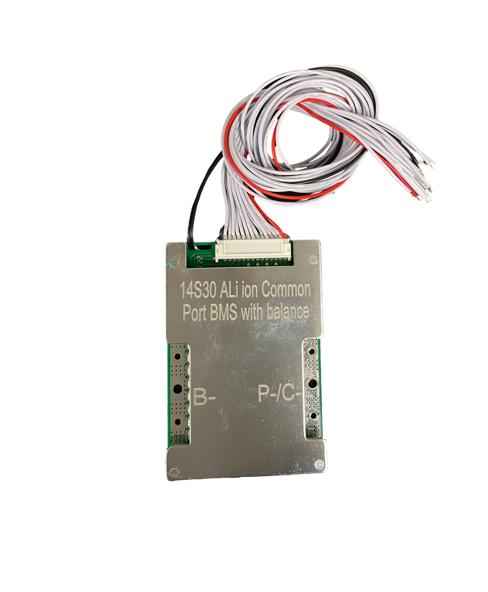
This is the BMS I have:
Note: These are not compatible with our bluetooth modules or computer interfaces. --------------------Here are 30a BMS units with 50ma balance function. We carry 3s-20s and both Lithium Ion (Li-Ion) and Lithium Iron Phosphate (Lifepo4). The lithium ion version also works with Lithium Polymer...

batteryhookup.com
Unfortunatley they don't provide any actual documentation on them, or link to the manufacturer's page for that specific model (or an actual model that could be looked up to find the docs), so we can't say what specific features and protections it has beyond the few limits they do provide on that page.
XiaoXang makes a lot of types and models, and they generally look similar enough that without specific info about the exact one in use, you'll have a tough time knowing complete details about it.
If you do want to replace it, you could, but I would recommend one that has bluetooth and a reliable easy-to-use app that is available in your language, so that you can at minimum do remote monitoring without opening up the pack to find out what's likely to be causing a specific problem. Some of them also allow changing some of the limits in the BMS...but I don't recommend changing them to make them more relaxed, only more restrictive (safer, more conservative).

")