kubark42 said:
The BMS should be cell voltage and temperature monitor-only. Charging and balancing will be done externally. <snip>
For better or for worse, very little safety is automated in aviation. Usually the machine's job is to alert the pilot to the problem and let the pilot sort things out.
Makes sense. There have certainly been plenty of (fatal and non) problems with safety reactions that *were* actually automated, especially when the pilots weren't aware of (or properly trained to react to) them.

The current hope is to slow charge through the balance connector, but getting a 15 cell charger could be a PITA.
If you really want to do that, your best bet is to get individual chargers for each cell group. You will need different voltage units for each chemistry, and you will also need a different number of them for each chemistry, as you will have a different number of series cells for each pack to get the same operational-level voltage from them.
Don't get cheap ones, because they won't likely have much (if anything) in the way of safety features.
Alternately you can design and build such a system, using an MCU of some type (Nano, etc) for each "single cell group" charger, that monitors the cell voltage and the charge current and terminates charge under whatever conditions you deem appropriate. If each MCU and charger PSU are electrically separate from each other, then it simplifies design quite a bit. The only thing you have to ensure is that the AC side of all power supplies in the system is completely electrically isolated from the DC side of each. If that is done, then it doesn't even matter which PSU/MCU unit is connected to which cell group, as long as it is setup for the right chemistry.
If you prefer to use existing "RC" chargers (the only multicell chargers I have seen myself), and can't find one with enough cell outputs, then you just need to make sure the ones you do use are powered by completely independent, completely isolated, external power supplies.
If you are charging from the balance leads only, and never the mains, this works fine, but you do have to make sure the chargers themselves actually *do* charge thru those leads. Some require the main leads to be hooked up too. For those, you'd have to make sure those leads are included in your wiring harness.
This is good thinking. Is the concern about the motor potentially going into regenerative breaking mode?
It is really about EMF and RF spikes that can come back thru the battery line, from any cause. Capacitors in the controller are intended to reduce this, but they don't always stop them, depending on usage and system design and controller design. It's one thing that can even blow up cheap controllers (probably not the kind you'll be using) like those typically found in ebikes and scooters and cheap motorcycles, because they often use FETs and other parts that can *barely* handle the battery voltage the controller is "rated" to run at.

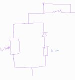
If you don't have any electronics (BMS FETs, etc) between controller and battery, then there's no worry about those, but the diode's reverse voltage spec must be higher than any spike it might see, or else the diode may fail. If it fails open, it means you don't have any capacity or current available from the pack it is in series with. If it fails shorted, it means you have no protection against current flow from the higher voltage pack into the lower one.
If you're not worried about the latter situation, then you might as well leave the diode out to prevent the former.

If there's a voltage spike on the rail it's not a bad thing if energy flows back into the Li-ion. Although it might be a bad thing if that energy blows up the diode and the energy has no place left to go.
If you have a diode in series with the Li=Ion, it cannot flow into the LI-Ion, as the diode blocks it.
My first reaction, though, is that the LiFePo4 pack will absorb any spike and thus the diode could only see high reverse bias voltages if the LiFePo4 pack is disconnected (blown fuse?) AND there's a voltage spike. Which should never happen because if the LiFePo4 fuse blows the pilot should immediately shut down the motor as something clearly is not copacetic.
Most likely, that's the way it would work, since you have no electronics between the cells and the controller. (other than that diode). But it depends on the system internal equivalent resistances, capacitances, and inductances, and how they interact with the spike, it's rise and fall time, it's magnitude, etc. I don't know how to predict that, though you could test the system for it by inducing spikes in the finished setup (as long as the spikes don't exceed the controller's parts ratings).
Personally, I'd just use a diode that could handle twice the current and voltage I needed it to, as long as it wasn't many times the cost of one that was just barely adequate.

(or many times the size and weight, for this application) But I'm not an engineer--just an experienced technical "hack" that is tired of fixing stuff that blew up because it was built of too-low-rated parts.


