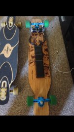
Brushless dual 6kw ALIEN Power system - electric longboard

brunotollot said:
Hi guys. First of all thanks to everyone for the great support. Richard and I are very grateful for that. It means that we are able to improve everything.
Also sorry sometimes for the late replies, but replying to all the mail and sending out all the orders take times.

We are working on the new products now. The new dual 3KW system is just amazing, words cannot explain.
Richard will post a video test soon.
We are also working on a sensored system,the ESC is already done and tested with some inrunner motors.
One of my supplier is making a sensored outrunner with internal PCB and SMD hall effect sensors. This for the all the requests I have had for perfect start and brake. Also the new program software is ready with the start power function. You can choose in % the power you want on the start. Very helpful...


Can you please tell us more about the new programming software? Is it out yet? I find the programming options to be one of the best features of your ESCs
 
Hi whilechukwuzout and thanks. Yes, the interface is easy, and the new one have the update side all in one, also easy for the users. Just few more days to fix a couple of things. The nice features are the power limit ( Lots ask for that, due to the power of all the kit ) and the start power setting in %.

20130906_003827 (FILEminimizer).jpg
 
Just received my GT2B transmitter and it's much better than the Hobbyking GT2. It's much lighter, a little smaller and built in battery. For an easy mod I think you could easily lop off the bottom (where the battery lives) and get 3 NiMH batteries (might need to be AAA) into the handgrip - you would also need to relocate the 3D channel button. You have to remove the rubber grip and unstick the "brand" sticker on the top to open it up (there's a few screws under the rubber) but my FlySky version came with a spare rubber grip so if you make a mess of it at least you have a spare.

Like the GT2 the GT2B has a big (guess about 45mm across) flat PCB mounted horizontally in the top which is going to make it harder to make the top of the control an awful lot smaller with a custom case but it could be improved a little I guess. Removing the base seems the easiest quick way to make it smaller.

Overall the the transmitter weight with the steering wheel and pot removed is only 250g with battery installed.

And no ... I don't work for Flysky or Hobbyking though if the latter would like to offer me a job where I get free parts ... where do I sign :)
 
simon-
I have been trying to tell everyone how light this controller is and easy to hold and includes a battery and is cheap to buy,reliable,includes a failsafe etc etc ..
This is the same unit I used on all my boards now .
Word of warning- this is the one I used to make my small alloy controller and it ended up losing signal- so be careful when modifying it..i personnelly found that if you take the wheel off the side it's not bad to hold and the battery base is great for standing it up on.. the problem as you say (and this is the same with all the contollers) is the large PCB on the top with all the trim buttons..which we just don't need but RC user do!! so unless you want to order a 10,000 order run -were not going to get a smaller pcb.. :cry:
 
I'm in the same boat ... broke my GT2 by messing around with it too much and maming the antenna. 2.4GHz is a picky frequency and it's so easy to upset wired antennas. I have the advantage that if I repackage it I'll be putting it in a 3D printed case - all plastic - no shielding or unintended interference planes.
 
I run mine up beside the batteries. I'd keep it away from the ESC and especially the motor as they will generate the most signal noise.
 
torqueboards said:
I just recently got a GT2 as well and was shocked at how small it was. Haven't used it yet but will soon.

You mean GT2B (comes with rechargeable battery)? Unlike GT2 which is a bit bigger and a lot heavier with 12AAs powering it.
 
Well I went over to visit Bruno this week and had a go on his dual 40mm -wow!!!! so much power for such small motors!!
The thing is a little wheely machine that turns on a dime!!! Its a 33" Earthwing deck with 83mm wheels,dual rear 40mm motor 12Tx44T gearing all on the new (prototype) caliber mounts. I was running a 6S battery on this short vid and we had to set the acceleration to soft!! its just wants to pull wheelies on med accdeleration.. the deck has got an enormous kick though but it was fun - i only had my helmet and no pads- :( im gunna practice the eskate-manual!! when i get home)
As you can see from the vid (please ignore my beer belly!!lol) there's no cogging from standstill and it pulls smoothly up to top revs..
I've brought it home with me to do a bit more testing and more vids and with the 5S battery I had 18-20mph on the GPS so i think 22-24mph with the 6S not bad for a 4.7KG machine!!
Brunos done a nice job on the ESC - (again)
[youtube]X-IHaTW3ELU[/youtube]
 
Just wanted to post some pics of the new cases Richard made me, there great still got to trim them a bit but there so neat and small
image.jpg
image.jpg
image.jpg
 
Nice setup!

Guys, does the length of the wires from the engine to the ESC matter? I am mounting an engine on the front truck and one on the rear. I am thinking to place both ESC on the rear side of the board (top mount) and run the cables from the front to the rear (the battery is placed in the backpack). Would that affect the ESC/battery?
 
Silenthunter said:
Nice setup!

Guys, does the length of the wires from the engine to the ESC matter? I am mounting an engine on the front truck and one on the rear. I am thinking to place both ESC on the rear side of the board (top mount) and run the cables from the front to the rear (the battery is placed in the backpack). Would that affect the ESC/battery?


I don't think it matters about the length of the wires, over longer lengths resistance will make voltage drops but not in the length we are talking, but you will be running 3 10-15 awg wires along the base of the board, I would mount the esc's next to the motors, and have the power cables meet where you want them to a Y splitter, but you will also need to run your receiver wires, I would personal mount battery and all under the board, because if you have to dismount the board quick your then going to still be connected to the board, if you implement a quick disconnect plug and the get the cable Court and it disconnects lots of esc's and motors tend to lock up and then you end up on your face. you also have a tripping hazard, and you battery plugs spark every time you connect them and ppl say it's not good for the esc, some say different, all that I know is it destroyed my banana plugs after a while.

Not saying don't do it not saying it can not be done but just saying you have a lot to think about:)
If you get it to work let us know post pics coz I'm sure there's some ppl who would like to do it:)

If you haven't ordered parts yet I would wait for the 40mm motors they are good:)
 
I have my board done. I am making my second board with laGrange kit motor front and rear. Now I modified the truck and made the hanger wider. From 6'' to 8" which brings the total from 11" to the 13.75 inch width. I am thinking to run the cables from the front to the rear and place both ESC right next to each other. I can't and I don't want to place any batteries underneath. I use drop through deck and there is no room for anything. That is why I am placing the ESC on the top of the board. Just wanted to see if anyone did this before. I don't think there is any harm to the ESC but wanted to hear others people opinion.
 
Silenthunter said:
I have my board done. I am making my second board with laGrange kit motor front and rear. Now I modified the truck and made the hanger wider. From 6'' to 8" which brings the total from 11" to the 13.75 inch width. I am thinking to run the cables from the front to the rear and place both ESC right next to each other. I can't and I don't want to place any batteries underneath. I use drop through deck and there is no room for anything. That is why I am placing the ESC on the top of the board. Just wanted to see if anyone did this before. I don't think there is any harm to the ESC but wanted to hear others people opinion.

No harm:)
 
Silenthunter said:
Nice setup!

Guys, does the length of the wires from the engine to the ESC matter? I am mounting an engine on the front truck and one on the rear. I am thinking to place both ESC on the rear side of the board (top mount) and run the cables from the front to the rear (the battery is placed in the backpack). Would that affect the ESC/battery?

I'd really advise against the entire wire thing. There are times I have fell on accident due to the pavement on the road which is sometimes unpredictable. Last thing you want to be is connected to the board when you fall and end up falling over the wires and face planting and/or pulling the wires out of the board itself and kicking the board home. The battery underneath the board is not bad at all and you have the freedom to walk around.

Imagine going to a store with your board in your hand and having to wrap your wired controller somewhere. It's a headache, I think.
 
Silenthunter said:
I have my board done. I am making my second board with laGrange kit motor front and rear. Now I modified the truck and made the hanger wider. From 6'' to 8" which brings the total from 11" to the 13.75 inch width. I am thinking to run the cables from the front to the rear and place both ESC right next to each other. I can't and I don't want to place any batteries underneath. I use drop through deck and there is no room for anything. That is why I am placing the ESC on the top of the board. Just wanted to see if anyone did this before. I don't think there is any harm to the ESC but wanted to hear others people opinion.

I think I've seen someone with top mounts and with the LaGrange there's a lot of the top mounts. It can be done.
 
Hi guys, just a quick post to reply to all the request about the sensored system. It will be ready in few weeks, and the cost will be around 15% more compared to the normal system. The main difference will be the brake and the ability to keep the board still in the hills after stop like on the Mountain board project to . In the end both system are very reliable and efficient so the sensored one in my opinion is suggested for users who need lots of brake and for the users who live in area with lots of hills with steep gradients
Now i would like to take this opportunity to explain why we need time, because customers ask everyday about news. Guys,.. to develop a system is not as easy as you think. This take lots of time, and lots of money. The sensored system development cost so far is nearly £2200 . 10x 42mm motors, 10x 50mm motors, 10x 63mm motors. on the motors prices you need to add 200 pounds for the sample fees, that actually is not too bad, due to the orders we do with the supplier. then there is the PCB sensors mounts fees and the delivery. Now, after that (£2200 ) we have to add the ESC, the batteries and wiring. Then starts Richards job, due to the different gearing configurations and belts lengths ,wheel size etc,Richard may need to redesign the kit, make a prototype, test it,make it again if necessary then when hes happy with the final design order in quantities with a Min order quantity required, so this is the explanation for the time we need to do that.
Again we really appreciate all your support and what we want to do is to provide different kit's for different users needs, with the ability for the users to choose their own board that more fits there requirements.

Also someone post that Alien Electronics LTD speed controller, it is actually a product by others company. Well, he discovered the hot water. Joking apart, nothig to say to this guy, i think people already know.
I wish i was able to do ESC, motors, Batteries etc. I'm a distributor and i love to do electric project for give the best and professional supports and advice to my customers. Of course the product i sell are made by other companies. He maybe need also to know that develop products is not easy as he think, and for find the best results between motors, controllers, batteries etc, if you working with an overseas companies, you need to send lots of products you are using, like motors, to find the perfect mach between them, and again, it is not "free". This company was with about 8-9 firmware for their ESC before starting the business relation. Now the list is around 25-30 different firmware. Anyway, just another explanation.

Here an example of "Alien PCB" Used for the big HV ESC, made in MOQ (not cheap)

Thanks again for the support guys.
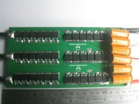
Alien 36.jpg
 
My 270kv 40mm motors arrived ready for testing, also will soon get Bruno's 42mm 300 kv motors so I can test the differance, we think the 300 kv will be plenty if power and torque with out putting these little motors into a situation of being under to much strain:)
 
Hey Bruno and Richard , you're doing a fantastic job !! We are so numerous, from many countrys to follow your progress , and we will sure wait the time needed to order the final product : )
So take your time , dear friends , I'm sure a lot of us can wait patiently....before riding quickly !! All the best , Eric .
 
well I'd thought I'd just post what I've been up to for the past few weeks while i wait for my CNC shop to finish all the Caliber mounts ..Ive been resurrecting the Hyper EV with a new arming system and cover.. actually I have been riding my dual 50mm for the past few months I'm a bit scared at getting on the 'beast'!! lol
so here's a quick slide show of the makings of a new battery box and arming switch (using an Anderson plug)- and best of all the info I give is for free!! no $30 dollar fee here... :?
And as I'm sure you all know-if you guys need any help or info about building your DIY electric skateboard..don't be afraid to ask..were all here to help on the forum..
Test fit
IMG_1178_zps508cdd04.jpg

V2 base
IMG_1180_zpsef5fdff4.jpg

V3 base
IMG_1182_zps3b0a2c44.jpg


IMG_1183_zps530becee.jpg

IMG_1184_zps6addd7fe.jpg

IMG_1186_zps3e34ae32.jpg

Dzus clip added
IMG_1189_zps81514fa1.jpg

IMG_1190_zps4a705a1f.jpg

IMG_1195_zpscb227d73.jpg

IMG_1199_zps2e0bab35.jpg
 
Back
Top