Build your own CD battery tab welder for about $100.00+-

Terramir, you are busy offending me here and I don't like it but I will answer a couple of your offending questions. You were asking questions in this forum a while ago and now suddenly you are the GURU......mmm very strange.....anyway, I am an electronic engineer and to build a "very accurate" capacitor meter is very easy. I don't know how you test your capacitors but you might want to go over your calculations again. You also mentioned that the capacitors that you tested blew a gasket at 17.5 volt...go look at my video....the reading on the LCD display on the left is the capacitor voltage and the one on the right is the power supply setting.....I did not see any smoke when I turned it up to 20 volts....haaa maybe I missed it...ohh well :lol:
Ps. You might want to go look at the schematic again before making any accusations.
 
caleb7777 said:
ugh

admiral steel won't deal with non-US accounts

Does anyone have some nickel tabbing I can buy off of them. I only need enough to test the welder and play once I build it.

PM me thanks
you try sunstone engineering http://www.sunstoneengineering.com/site/pages/sales they do ship internationally etc.
GL
terramir
 
Hi Fritz - - I think there are a lot of readers here who would LOVE to know which brand of capacitor you found to be performing so well. So many of us have purchased ones that are not within a country mile of reaching the specs claimed by the manufacturer.

If there is a really good one out there, they deserve our business - - Especially since the majority of them apparently DON'T meet specs.

Pleeze to share??
 
oldusedbear said:
Hi Fritz - - I think there are a lot of readers here who would LOVE to know which brand of capacitor you found to be performing so well. So many of us have purchased ones that are not within a country mile of reaching the specs claimed by the manufacturer.

If there is a really good one out there, they deserve our business - - Especially since the majority of them apparently DON'T meet specs.

Pleeze to share??

It is a 3 farad Volfenhag cap. I have to open my welder to get the model. Here is a link on ebay (its not the same as mine but more or less the same specs) that has an ESR of 0.00195 and an operating voltage of 16 to 23 volt. It is hard to tell if the voltage gets clamped by the electronic circuit or is it the cap that can work between 16 and 23vdc.
http://cgi.ebay.com/NEW-ZX-4-FARAD---Volfenhag-4.0-Farad-Digital-Capacitor_W0QQitemZ110407777285QQcmdZViewItemQQimsxZ20090627?IMSfp=TL090627141006r33345
 
Fritz,

i have also reviewed your schematic. i like the unusal approach you have taken to turn off the SCR. Terramir is right in one respect though. the finished price will be more than $100.

of everyone here who has tried a DIY welder how many have only spent $100? please remember to add up the initial cost of the junk used you already had to hand. you paid for the stuff when you acquired it.

let's see we need a BIG capacitor, BIG SCR, power supply and a couple of support circuits. add some really heavy wiring and electrodes. $100, doable if you spend a couple of months at swap meets and hunting down the perfect deals on ebay. $100 could easily be spent on any single item. with inflation and all, the $100.00 is more descriptive than realistic.

given the profesional looks of the final package and the welding results on the video, even if Fritz spent $500~600, it was money well spent.

to my mind the reason for these forums is the dissemintation of knowlege gained by others experiments. i do not think of them as step by step instructions for assembling a "KIT" product. no one here is absolutetly right or wrong. even knowledge of failure is important. i will eventually build a welder. even if only to bring back to life all of those "DEAD" power tool packs i have in my personal collection.

in all likelyhood i will not build a duplicate of Fritz's or Terramir's or Docnoj's welder. likely it will use ideas gathered from all of those as well as others. if i'm lucky i might even include one or two of my own.

okay, it's Sunday, that my excuse for a sermon. after all of that long winded crap, finaly the point i was trying to make - no need for anyone to belittle or talk down to anyone else. i'm weary of some of the recent antagonistic posturing and stuff. i hope everyone else feels the same way.

rick

or am i the only one who can smell the testosterone?
 
Thanks for the update, Fritz. I have a pair of the Volfenhags in my just completed welder. Mine are rated at 2.0 Farads each, but I've made no attempt to measure their true capacity.

The "beta tests" of the welder have surpassed my expectations tho. I'm not doing anything all that challenging - - tabs on sub-c battery packs. The welder seems to do just great with both .005 as well as .010 nickel tab material. Getting my best welds at only 11 volts or thereabouts - - So I guess my Volfenhammers are doing OK
 
idea from that CD cutter video - has anyone with a completed welder tried using TIG welder electrodes? they are usually a very hard Copper/Tungsten/Molybdenum alloy. the Tungsten component should prevent sticking to non-ferros metals like Copper or Brass.

also should be relatively cheap and available from local welders supply stores.

comments?

rick
 
Fritz said:
Terramir, you are busy offending me here and I don't like it but I will answer a couple of your offending questions. You were asking questions in this forum a while ago and now suddenly you are the GURU......mmm very strange.....anyway, I am an electronic engineer and to build a "very accurate" capacitor meter is very easy. I don't know how you test your capacitors but you might want to go over your calculations again.
Hmm easy maybe, but most of us lack the capacity to measure one above 4000uF very accurately. there are two ways people estimate the actual capacity of a large (>4000uF) capacitor. One is the 1RC method,which as you well know as an electronic engineer is the time it takes for a capacitor to reach 63.2% of the known charging voltage. If you know the charging voltage and it's not one of those supplies that rise in voltage to supply constant current your in the game. the math there is T=RC the other way is a discharge through a known resistor from let's say 11V to 5V the formula would be C = -t/(R*ln( Vt/Vi )) now my cap bank (2 parallel main caps out of a hybrid cap) will give me a calculated capacitance of 1.58F when I use the 1RC method and well 1.22FR when I use the discharge method. capacitor leakage and well depression on the voltage source are the problems here so my cap bank is somewhere inbetween.


Fritz said:
You also mentioned that the capacitors that you tested blew a gasket at 17.5 volt...go look at my video....the reading on the LCD display on the left is the capacitor voltage and the one on the right is the power supply setting.....I did not see any smoke when I turned it up to 20 volts....haaa maybe I missed it...ohh well :lol:
Ps. You might want to go look at the schematic again before making any accusations.
[/quote]
Hmm dude your not getting it I didn't ask questions to offend you but for us in this forum to learn, you mentioned that your cap is a 3F volfenhag, well you picked the brand that so far all of us know as the best one yet, but even then most people were getting like 30% less the 1.5F one the thread starter used in his first battery tab welder he estimates he got about 1 real farad.He (the thread starter) blew a "gasket at 17.5V/2Amps (charging) on his second revision of the tab welder. As for your schematic it is difficult to read to say the least that e-paper crap seriously put a hamper on analysis, honestly I dun know how your welder works because I cannot find the way you stop the scr once you start it. We all know of onsemi's application note but that requires 2 scr's I really think you have something great going on here, but we all like to know how you stop the cap from discharging through the scr once it starts.
I don't want to offend you but we all would like to upgrade our welder with pulse control as of now the only way we know how to do this is with a mosfet driven setup that need alot of parallel mosfets that can blow-out at times, turning an scr on and off at will would be a great solution, but we all lack the know-how to do this cheaply short of using two scr's we don't have a method. help us post a schematic of just the scr part of the circuit, anyone here can find alternative ways of turning that circuit on and off (different pics, using timers etc.) we just need more knowledge about the scr control part of the circuit, ergo what turns your SCR off discretly.
my $.02
terramir
 
rkosiorek said:
Fritz,

i have also reviewed your schematic. i like the unusal approach you have taken to turn off the SCR. Terramir is right in one respect though. the finished price will be more than $100.
wait a minute you understand hopw he turns off the scr? this is what I was looking for this whole time share the knowledge, as of right now I have not seen a method except for onsemi's way. I looked at that schematic of fritz's but with that e-paper I'm just not getting it.
help and explain please
we are here to learn
terramir.
 
he does it very simply. he has a contactor switch in series with the capacitor bank/points/SCR. on his schematic the coil for the contactor is labled "CR" and the switch as "S1". at start the contactor is closed and current flows to the SCR. when the contactor opens the current to the SCR is cut off. simple eh. maybe a bit old school forklift tech, but what the heck, if it works..

initially i though a contactor may be expensive. but in reality it is not much more than a second SCR.

rick
 
That is the problem Terramir, because one guys cap did not test right and one guys cap blew up at 17,5 volt does not mean that all the caps will do that. Also just because one guy said that you have discharge the cap to 63.2% of the charge voltage ....let,s see so some people discharge the caps only 36.8% from the charged voltage or make a mistake working out the percentage . That is so wrong. I don't work with percentage because it is so far out, I use a constant that I multiply to get the correct voltage that you have to use to get the time. One guy in here was using Mosfets to control his welds and i can tell you that It takes more than just putting a voltage onto the gate of a Mosfet to make it turn on the correct way. I have already build Mosfet controlled welders and I decided to make it easy for everyone and use a contactor to turn it off. Don't think its easy and old school Rick :) remember contactors are very slow and how do you make a 1 millisecond weld with a contactor that takes 30 milliseconds to fall out.
I took a 1Farad Pro-Ice cap this morning and discharged it with a 32 Ohm resistor and to proof to you that most of these caps are close to the manufacturer Size I'm including the wave:View attachment 1Farad.bmp

This cap was discharged from 11.8 Volt with a 32 Ohm resistor and it took 31.2s to reach 4.4 Volt...the voltage should have been 4.341 volt.Calculate that and you'll see that you are very very close to 1 FARAD.
Ps. For the people that don't understand the above.
The red line at the bottom is the 0 volts and every block that goes up is 2volt. This is not shown but the actual voltage was 11.8 volt. The purple line on the left is the start of the discharge and the purple line on the right is when the cap voltage was 4.4 volt and if you look at the the menu to the right then you will see that the time between the purple lines is 31.2 seconds.
 
oldusedbear said:
Thanks for the update, Fritz. I have a pair of the Volfenhags in my just completed welder. Mine are rated at 2.0 Farads each, but I've made no attempt to measure their true capacity.

The "beta tests" of the welder have surpassed my expectations tho. I'm not doing anything all that challenging - - tabs on sub-c battery packs. The welder seems to do just great with both .005 as well as .010 nickel tab material. Getting my best welds at only 11 volts or thereabouts - - So I guess my Volfenhammers are doing OK
You are welcome :)
 
Fritz said:
<snip>
Don't think its easy and old school Rick :) remember contactors are very slow and how do you make a 1 millisecond weld with a contactor that takes 30 milliseconds to fall out.
<snip>

issues like that come up very often in motion control and process control. it often takes one thing an awful lot longer to happen than the other. but in the end both must be timed to stop at the same time.

so the solution is to fire the contactor, wait 29mS and then fire the SCR. there is then a 1mS overlap where things get done. :)

and why does OLD school have to mean BAD school? I just meant that sometimes i get so caught up in the newer, often "better" solid state ways of doing things i forget that back in grandpa's time there was a simpler way of doing things.

rick
 
rkosiorek said:
Fritz said:
<snip>
Don't think its easy and old school Rick :) remember contactors are very slow and how do you make a 1 millisecond weld with a contactor that takes 30 milliseconds to fall out.
<snip>

issues like that come up very often in motion control and process control. it often takes one thing an awful lot longer to happen than the other. but in the end both must be timed to stop at the same time.

so the solution is to fire the contactor, wait 29mS and then fire the SCR. there is then a 1mS overlap where things get done. :)

and why does OLD school have to mean BAD school? I just meant that sometimes i get so caught up in the newer, often "better" solid state ways of doing things i forget that back in grandpa's time there was a simpler way of doing things.

rick
You got it....like i said before i did this so that everyone can build a pulse width control welder and like my grandpa always said "Every difficult problem is easy when solved" :D . I am busy with a small solid state circuit that you guys can connect to your SCR's to turn them off so keep an eye on my blog for updates.
 
Fritz said:
That is the problem Terramir, because one guys cap did not test right and one guys cap blew up at 17,5 volt does not mean that all the caps will do that. Also just because one guy said that you have discharge the cap to 63.2% of the charge voltage ....let,s see so some people discharge the caps only 36.8% from the charged voltage or make a mistake working out the percentage . That is so wrong.
Ehh I bought an absolute USA Cap that was rated 2 Farads, and according to the 1rc method of charging (not discharging that's the other way of calculating) it only had 0.6F and you could tell by the welds as well
Fritz said:
I don't work with percentage because it is so far out, I use a constant that I multiply to get the correct voltage that you have to use to get the time. One guy in here was using Mosfets to control his welds and i can tell you that It takes more than just putting a voltage onto the gate of a Mosfet to make it turn on the correct way. I have already build Mosfet controlled welders and I decided to make it easy for everyone and use a contactor to turn it off. Don't think its easy and old school Rick :) remember contactors are very slow and how do you make a 1 millisecond weld with a contactor that takes 30 milliseconds to fall out.
I took a 1Farad Pro-Ice cap this morning and discharged it with a 32 Ohm resistor and to proof to you that most of these caps are close to the manufacturer Size I'm including the wave

This cap was discharged from 11.8 Volt with a 32 Ohm resistor and it took 31.2s to reach 4.4 Volt...the voltage should have been 4.341 volt.Calculate that and you'll see that you are very very close to 1 FARAD.
So the pro ice brand is also a brand that seems to be true to the actual ratings it is good to know, we should start a data base I understand that you have better equipment than most of us here, and using a contactor that is released in a timed method is actually a stroke of genius. I have been thinking about another solution to this problem myself since to turn off an scr we must stop the current flow and scr's will not disengage, unless the current stops flowing I thought of a method that should work as well as using 2 scr's (which cost a pretty penny).

My idea is to do the same thing that the second scr does with a power mosfet the second scr in the onsemi application doesn't carry much current it just serves a blocking purpose. Now since were using somewhere from 10 to 20V here and the scr conducts the main current from the cap, what's to stop us from applying a short higher voltage but low current to reign in the scr? let's say 24V 10mA. that low current has a higher voltage so it should stop the current flow in the scr. since the trigger pulse to the scr is also released it should stop the scr dead in it's tracks or shouldn't it. what you guys think?
terramir
 
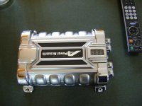
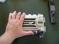
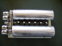
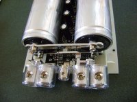
I got my capacitor today and yeah it was as was said probably two cans and a bunch of supercaps the small caps are rated 10F 2.4 v each, the large ones are unmarked. What is the easiest way for me to find the true capacitance on those big cans?

Do i need to strip the cans out and leave the rest for this to be used as a welder or can I just hook it up as is. I would like to keep the voltage reader. Should I strip the small ones? Will there be much loss if I don't?

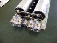
I know it has been recommended, but I am wondering why? The caps go directly to the main bus bars and out. Also, the manual only rates these 16v wth 20v surge, online shows 12-24v operation through the vminnovations website.

my guess is that the buss bars are aluminum but its hard to tell since everything is spray coated. Do I need to change the buss bars?
 

Attachments

  • DSC00189.JPG
    DSC00189.JPG
    66.9 KB · Views: 3,717
  • DSC00190.JPG
    DSC00190.JPG
    58.1 KB · Views: 3,718
  • DSC00191.JPG
    DSC00191.JPG
    67 KB · Views: 3,718
  • DSC00192.JPG
    DSC00192.JPG
    80.1 KB · Views: 3,719
  • DSC00193.JPG
    DSC00193.JPG
    81.4 KB · Views: 3,714
I bled it off with a 150 ohm resistor from 14.85 volts and recorded the voltages at the end of each minute for 5 minutes.

using V=Vo*e^(-t/RC)

I got 1.3 to 1.4 Farad at each interval. Disappointing at best.

Is this formula right?

The results are slightly lower than true though because the onboard circuit pulls juice constantly as well slowly. Caps together may add to 1.5 F at best according to my results
 
the circuit board and super caps will hurt the performance as a welder. you should ditch those. and just run the two big cans. the ESR of those supercaps is way too high for a fast discharge.

the bars could be aluminium, but they could also be nickle plated brass or copper.

the formula is correct. you should also measure the capacitors charging up.

rick
 
use the 1rc method during charging from a non volitile power source (like a lead acid battery with two voltmeters to determine the capacitance,
that means you need to know the time it takes to charge to 63% of the power sources voltage. if you use a regulated psu it will up the voltage and current in order to regulate back to the choosen voltage so a leadacid is best for testing purposes.
terramir
edit and yes get rid of those supercaps, the'll kill ya everytime. btw 1.5F is more than enough for most projects
 
Hello Everyone:

By way of introduction, I'm looking to build a CD battery tab welder. I've done the googling and looked at Phil Pemberton's work, and at LEDHacks.com and some other ones, read/looked over this whole thread. I'm a retired EE. Among other things, I used to design power supplies, but I've never used an SCR before, nor done much with "high" power pulse circuits, so I'm in learning mode here.

I've ordered my SCR from ebay, an S23AF4B made by IR. Getting datasheets is a challenge, but I found a generic one for this one, 400V, ITSM of 4400A to about 5300A depending on 50/60Hz waveform and whether a voltage is applied afterward or not. It's a hockey puck package. I've figured out how to mount it and how to apply the torque to get something less than the correct mounting pressure. If anyone else needs this info let me know and I'll post it.

I have read with particular interest the discussions on terminating the pulse before the natural complete RC decay. Maybe I don't understand the operation correctly of the RC/SCR/FET shorting circuit, but here is my problem with it. If the current through the primary SCR is terminated too early, it will be quite large. At that point, the shorting SCR/FET and cap will have to dump the entire primary current at that time in the short transient waveform. The peak current is the killer here, both for the cap and the SCR/FET. And if we wait 'till the primary current is low, we may as well let it go ahead and time out for the full waveform; in other words, if the circuit won't handle the full current, it won't work.

I'm really looking forward to seeing Fritz's schematic when he gets it updated. I understand the contactor concept in general, but not too sure about how he is using the transformer. I'd like to check out the circuit waveforms on that one. Seems like a regular 60 Hz transformer core might be up to the task, but it will take a really big one to keep from saturating the core, maybe. Also, it's hard to see how the contactor doesn't get welded shut, but again I'll have to see the schematic to start to understand.

Looking forward to learning more from this group. It is a really cool thread.

Thanks,

Dave
 
dbird said:
Hello Everyone:

<snip>

I've ordered my SCR from ebay, an S23AF4B made by IR. Getting datasheets is a challenge, but I found a generic one for this one, 400V, ITSM of 4400A to about 5300A depending on 50/60Hz waveform and whether a voltage is applied afterward or not. It's a hockey puck package. I've figured out how to mount it and how to apply the torque to get something less than the correct mounting pressure. If anyone else needs this info let me know and I'll post it.

<snip>

Thanks,

Dave

Dave,

i was also looking at some hockey pucks. what was stopping me was a simple mount and contact. i'd love to see how you mounted yours. please post pictures. we need more pictures.

rick
 
caleb7777 said:
Can I strip the caps and most off the board and keep the voltage indicator? How much would I lose?

that question cannot be accuratetly answered without knowing the wiring that is on the board. but i would guess that you could desolder them from the board. also check the board and see if there are any resistors in parallel with the caps. you should also remove those if there are.

rick
 
Back
Top