Build your own CD battery tab welder for about $100.00+-

"Using a surplus SCR to discharge it, there would be no easy way to control the pulse width other than by what voltage you start at. Once those babys turn on, they don't want to turn off. "

Today I've found fast turn off thyristors. For example P270CH04, 500A(6500A). Would this solve turn off problem or this is just one parameter that means no advantage?
Turn off time 12-15usec instead of 100us that my other SCR has.

And just now I read this" After the SCR turns on and is conducting significant forward current, the SCR stays on even if the gate drive is subsequently removed. Therefor, only a brief pulse of gate current will be needed to latch the SCR on. The SCR cannot be turned of by shorting and reverse-biasing the gate-cathode terminals of the device.
In fact, the only way of turning the SCR off is by momentarily reducing its anode current below a value know as the minimum holding current (IH). So it follows that turn-off occurs automatically in a AC circuit near the zero-crossing point at the end of each half cycle.

So with single SCR I can't control the pulse width.
 
I think the fast turn off ones still need to be zero current to turn off. It's easier to commutate them with another SCR.

I was doing a bunch a head scratching and came up with a few approaches.

If the cap charging was done with a FET instead of a mechanical relay, you could have the voltage fed to a comparator that will shut off the charging current as soon as the cap voltage reaches the desired set point. The set point could be adjustable over a wide range. This way, the FET could be in the hard switching mode and not have to throw off a huge amount of heat. This would also minimize charging time.

If the comparator was configured to have a major amount of hysteresis, the charging current would completely stop as soon as the cap hits the set point. It would come on again as soon as the cap is fully discharged.

Yet another approach would be to simply control the charging time with a timer. As long as the timer was consistent, the voltage should be too. If the supply is current limited, the voltage will be a nearly linear function of time.

On the discharge side, you can tigger a SCR gate through a capacitor to make sure the gate drive goes away as soon as the thing tiggers. This also compensates for voltage offset between the timing or tigger circuit and the SCR.

Using this approach, you could do a dual pulse circuit that was based on a pair of LM556 dual timers. One timer for each cap bank would control the charge level, and the other two timers would control the dual discharge cycle.

Below is a sample of a sequential delay circuit. This is not an acutal welder circuit, but shows the layout for a dual timer delay.
 
so the switch is used to trigger the first scr and this timing circuit? the output of the second 555 is used to trigger the second SCR? do i have that right?
 
Yes, basically. The first SCR could trigger directly from the switch or from pin 3 on the firs timer. I think you'd need a resistor or capacitor between the timer output and the SCR gate.
 
and the value of r1a and r1b would be chosen to set the delays.

R1a would set the time that scr1 would fire after the switch is closed acting more or less as a debounce circuit for the second timer. then R1b would set the delay between triggering of scr1 and scr2.

rick
 
Idea for the discharge part, controlling 6000A!
Why not to use 15 mosfets in paralel?
What if we used pin 3 to drive a huge array of say 15 IRFB4110 mosfets using some high speed mosfet drivers. Then we could set the pulse width with the first 555 setting resistor then out of the pin3 of the second 555 it would fire another array of 15 fets to fire the second pulse with width controller with the third 555.

IRFB4110 can survive aprox. 700A peak!
The total would be around 10 000A so they shouldn't burn.
Buying a HUGE single IGBT or fet is out of my budget.
Do you think that the fets would fire all at once and the current would spread eavenly or I'll be buring them one after another?


Here is yet another link where you can clearly see how the double pulse should look like. The energy delivered with the second pulse is 4-5x of the first initial pulse. First pulse cleans, helps adhere the electrodes and preheats, second finishes the weld.

http://www.sunstoneengineering.com/site/pages/dpInstructions
 
A bunch of FETs would certainly work. At 12-15v, you could use lower voltage rated ones that have a lower on resistance. As long as the buss bars that feeds the FETs are really thick, the current should be evenly distributed.

Giant IGBT modules can be found on eBay sometimes for cheap.
 
When driving 10 or even 15 mosfets one has to be careful so they all switch on and off at the same time otherwise they will blow. (not very nice)
To do so I've found a suitable mosfet driver.It's capable to drive mosfets in paralel by providing a high current capability (up to 6A) for the gates. It is LTC4441.
Hope I'll be able to locate a couple of them in the UK.
The advantage of using an array of fets instead of one or two huge SCRs with a capacitor bank is to be able to adjust a width of the impulse.
I haven't found anybody paralleling so many mosfets on the internet so any links and advise is always welcome. We are controlling 6000A shots, maybe more !
Another even more powerfull 9A driver for large IGBT and mosfets is here:
http://ww1.microchip.com/downloads/en/DeviceDoc/21420d.pdf
Lastly...irf2804 is probably the lowers RDS(on) mosfet available. Only 2mohn! 280A,and over 1100A peak! 10 in parallel should do. They are good up to 40V
http://www.irf.com/product-info/datasheets/data/irf2804.pdf
Since buying 50 irf2804 in D2-pack package(check the datasheet, smd size, soldered flat onto a heatsink or pcb) is MUCH cheaper than going for regular size I'll go for this option. I need about 24 of these fets for my project.
If any of you is interested in buying these beasts in the UK let me know. We can share the shipping. The price will be only £1.7 each. Including all (postage, custom tax, vat) No need to pay anything now !.
 
the reason for controlling the width of the impulse is to control the energy delivered. this could also be done by controling the voltage delivered by each pulse.

if i have one 1f capacitor charged to 6V and a second charged to 10V and fire each separatetly through a pair of SCR's i could ahieve the same result.

2 caps, 2 SCRs, 2 simple variable voltage regulators, 1 simple timer and a couple of relays would be a lot closer to the $100 budget than the alternative of 15 fets(3 dollars each) and a much more sophisticated timer and control circuit.

or am i missing somethng here.
 
digikey UK has them in stock less than 2pound each.

they also stock the IRF2804 at about 3pound each.

gonna be an expensive switch.
 
I'm after a pro like welder where you can mod the actual width of the pulse. This is important for welding coper to nickel,steel, brass. My welder will be slightly over $200 but will have some nice features.
8F caps, a lot ! of power( I hope) , adjustable 1st, 2nd impulse width and delay in between and voltage separate for both pulses of course. The price doesn't include double power supply. I'm importing some parts from the USA and the price could be lowered by these shipping charges. With adjustable double power supply and if in the USA one could make a pro like spot welder for around $250? (some parts of course from ebay).
So it does make some sense I think.
On digikey uk the price with no vat is 1.77 for 150! I don't want 150! For less than £75 order there is a handling £5 fee plus shipping £12.
To be honest I get lower shipping from the USA than from the UK and better prices. No handling fee too.
I'll rather order from overseas as I did before with IRFB4110.

So If I offer them for £1.7 total price plus £4.4 shipping.... it's less than 1/2 the price here!
EXAMPLE: 20 pcs From digikey uk: cheapest 2.84 (to220, smd are £3.6 each) x20 plus £12 shipping, NO handling (maybe they will charge extra £5) plus vat! = £78 to your door
from me: 20x £1.7 +£ 4.4 registered and insured postage = £38.4 to your door
YOU SAVED £40!

Note: I profit only by sharing the postage so I don't consider this post to be advertisement or similar.
 
Some Curtis golf car controllers use something like 35 FETs in parallel.
You can use multiple driver chips, so each one drives 3 or 4 gates, keeping the switching time fast. You could also probably just use a pair of transistors as drivers. You can drive many gate drivers from the same source.

I'm not sure if there will be a significant inductive kick back when you open the circuit. You might need some fast diodes across the load (backward) to prevent high transient voltages.
 
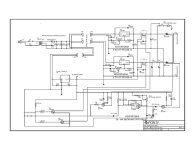
so seeing that i have a few SCR's and big Cap's i'd like to use them if i can. so here is my proposed schematic for a dual pulse SCR based unit. the only thing i really need to buy is the voltmeter. the rest would be out of my parts bins.

i recognise that the approach with gazillions of FETs has some advantages and i would probably would build one if i had a reasonable schematic to work with.

i'm really not sure about the Triggering and delay circuits. i think i did it right but original design is not my strong suit. any suggestions are welcome.

a couple of things sort of haunt me. would it be necessary to do some kind of precharge circuit for these big capacitors? or is the voltage low enough to not worry?
also i'm not sure if i got the polarity of the delayed trigger pulse correct.

rickSCR DUAL-1.jpg
 

Attachments

  • SCR DUAL.pdf
    30.1 KB · Views: 522
There might be a problem with the second pulse trigger. I think the output of the 555 will be normally low, except during the timing cycle. This would hold the second SCR on before the first pulse.

There should be a way to couple the tigger pulse with a capacitor so it only responds to a sudden change in voltage. I'll have to scratch my head a bit on that one...
 
i also realized that i had the PNP transistors that drive the SCR gates drawn with the emiter and collector reversed. they would never have triggered the SCR that way.

the corrected schematic is now posted.

i added the 100n capacitor and the 10k resistor to pin6 (threshold) of the 555 to stop it cycling once during power on. i also added a 100n cap in series with pin2 (trigger) to debounce the switch and prevent a false trigger. other than that it is a one shot delay. at least i think that it is.

rick
 
I think it will work now.

The 1k resistor on the pnp gate driver might need to be a bit lower depending on how sensitive the SCRs are. You could also just put a 10uf capacitor across it to give it a higher initial current.
 
okay the resistor value was lowered to 470R and i added the 10mf capacitors. both jpg and pdf schematics are updated in the original post.

rick
 
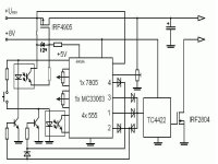
This is a sketch of a powerful (8 FARAD) mosfet dual pulse CD battery welder with a pulse width adjustment.
After talking to my good friend about using an array of 10 mosfets IRF2804 (in parallel) and a mosfet driver.:
We decided to use only one big cap. bank.
Ureg is 3-17V 10A originally 13.8V moded power supply
We want to limit the initial pulse only by the pulse width (length).The same will apply for a big second pulse.The voltage will be set the same for both pulses.
We hope that because we want to use mosfets to control the pulse width we will be able to fine tune the energy delivered for both pulses as desired/needed.
The resistance of 10 IRF2804 will be only 0.2mohm! If all works we will have a home made 10 000A solid state switch with the ability to switch on/off within a few micro seconds.
I can't wait to see if we will be able to weld coper to nickel/steel as a some pro welders can.
Our welder cost: mosfets 11pcs aprox $40
8F audio cap bank ebay $90-$120
other electronics $20-$40
pulse power supply(13.8V, 10A) ebay $40
wires, electrodes ,other building material $20-$50
Total $210-$290 (higher price includes the postage of some parts from the USA to the UK)
 
wow, i can't wait to see the actual schematic. maybe i'll hold off building my scr device.

i'd like to see how the power supply is modified as well. perhaps i could use the same idea to modify a computer powersupply to become a variable supply.

rick
 
Cool.
One big challenge will be the connection of the FETs to the bus bars. The buss bars must be very heavy copper to keep the resistance down. Soldering to a really big chunk of copper takes a lot of heat and doesn't happen fast. If the buss bars were connected at opposite ends (this needs a drawing), you can compensate for the buss bar resistance to keep the current in the FETs evenly distributed. Imagine a pair of parallel copper bars, with wires attached to one end of each bar to make the circuit. If the wires come off the same side, the resistance of the bars will add and the FET closest to the wires will take the most current. If the wires attach from opposite ends, the total bar resistance that each FET sees will be the same, so the current will be evenly distribute.

You might be able to heavily tin the bars in advance, then tack the FET legs into the solder later. This should allow for shorter heating times to prevent cooking the FET guts.
 
fechter said:
... you can compensate for the buss bar resistance to keep the current in the FETs evenly distributed. Imagine a pair of parallel copper bars, with wires attached to one end of each bar to make the circuit. If the wires come off the same side, the resistance of the bars will add and the FET closest to the wires will take the most current. If the wires attach from opposite ends, the total bar resistance that each FET sees will be the same, so the current will be evenly distribute....

After making a drawing I know exactly what you are talking about. How simple and effective! Thanks.
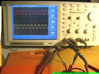
I'm also getting my first oscilloscope for this Christmas. It's Digital 7.8"Color 25MHz Oscilloscope OWON PDS5022 .
( I edited out the info that wasn't important for building the welder to keep the post short)
 
it looks like all of the high current stuff is going to be expensive as well. finding some in a small town will also be a problem. i priced out some 0.250" thick X 1.000" wide C110 copper alloy buss bars. locally the supplier wants about $10.00CAD per foot. and i would need a foot and a half or so. i found that the online prices were cheaper but once you add shipping it comes to almost the same amount.

i don't think that soldering to thick copper bars like this is an option. copper transmits heat so well and retains the heat for such a long time that you would exceed the soldering heat that the fet can survive. spot welding the leads or better yet clamping them between a copper strip and the buss bar is a much better option. the drain connection is easy as it is the back of the SCR and you could just bolt the fet to the buss bar without insulating hardware. then the heat sink can be bolted to the buss bar with insulating hardware. the copper will actually conduct heat better than the aluminum heatsink anyway.

rick
 
You might try going to a metal recycling place to find used copper buss bars.

Right about the drain connection. Just bolt the heat sink tabs directly to the bar. The source connection could be a bolted / clamped kind of connection. As long as the clamping force is good, the resistance will stay low. It shouldn't be too hard to drill and tap holes in a copper bar, then you could use a metal strip like a cut down washer to clamp the FET leg to the bar.
 
copper is a soft sticky material to machine. you definitely need some taping oil to ease the cut when tapping the screw holes. you also need to only advance the tap about 1/2 turn at a time and turn the tap back about 1/3 of a turn to break and clear the chips. every few full turns it would also help to back the tap out completely and clean out the swarf. a bit of patience is needed to prevent breaking the tap.
 
My friend and I were working on the schematics today .
It's nearly finished now.
One extra separate "delay" 555 timer will make sure that you can't misfire when charging the cap. You set the time for example 3 sec in according to your power supply charging capabilities.

The clamping will be done as you say !
Santa was here with the oscilloscope today.
 

Attachments

  • osc2007.jpg
    osc2007.jpg
    127.3 KB · Views: 2,264
  • nemo welder 3.JPG
    nemo welder 3.JPG
    37.2 KB · Views: 6,756
Back
Top