number1cruncher
1 kW
Recently, I order a few controller kits from Keywin to pass the time during the Fall and Winter months. I asked for both 12 FET Sensorless and 18 FET Sensored kits. The 12 FETs were pretty familiar, with a couple new updates, such as silk screening the recommended component values. I guess Keywin got tired of people asking, haha. They were EB312 boards. However, the 18 FET boards look quite different. There is an area at the right side of the board for a secondary power supply that Keywin advised was for voice functionality. Something to explore in the future, as this post is how to build the controller to have the usual functionality we are accustomed to using.
Here is the KH318-FS-1 board. Keywin added the primary ps components and some smaller caps around the board.

The first thing I do is to install the FETs on the heatsink bar to align their legs and tighten them down. Waiting until the board is populated makes it difficult to tighten the FET screws, especially near the wire exit cover. Also, it is more likely to damage a cap, pull a wire or cause other damage when trying to access the screw head with the screwdriver.


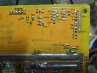
Next I added solid 12awg copper to the power traces. On the smaller boards I use a single wire, however on the 18 FET there is room to place a parallel set in a couple places.


View attachment 17
After all the copper has been added, I installed the phase and power wires.


Next I added the remaining large caps, threaded the 10awg wires through the end cap and addes the signal wires.


View attachment 10


After all the heat and added mass, the boards have a tendency to bend. To correct this a little, I start soldering the FETS on one end closer to the FET body working my way to the other end, using leverage to straighten the board. A principle carpenters use to create straight frames with bent 2x4s.


I forgot to add the CA wires during the signal wire step, so they were added.

Next glued down the caps with RTV sensor safe silicone.

With all the added copper and solder the power traces touched the case in a few places, so I added some plastic sheeting between the board and case for insulation before tightening the heatsink screws. One of my early mistakes was to not do this and it did not end well. That board was not quite touching the case, but a nice pot hole caused the board to jiggled enough to make contact. Doh!

The last build step was to terminate the phase and power wires. I used 45A Andersons. Thankfully, Keywin included the connectors on the signal wires. 8)

View attachment 1

With the build completed, I tested the controller and it worked fine. Usually I reprogram before testing, but I do not have any programming software specific to the KH3XX boards and was worried I may brick it. However, curiosity, the lack of certain functionality and an obviously low amp setting prompted me to try reprogramming the controller. The EB3XX software worked fine. I will try to get new software and will report back if successful.
Has anyone else seen these boards and know of any new functionality aside from the voice function? I was hoping for proportional regen like on the EB8XX boards from e-bikekit.com a few years ago, but so far have had no luck.
Here is the KH318-FS-1 board. Keywin added the primary ps components and some smaller caps around the board.
The first thing I do is to install the FETs on the heatsink bar to align their legs and tighten them down. Waiting until the board is populated makes it difficult to tighten the FET screws, especially near the wire exit cover. Also, it is more likely to damage a cap, pull a wire or cause other damage when trying to access the screw head with the screwdriver.
Next I added solid 12awg copper to the power traces. On the smaller boards I use a single wire, however on the 18 FET there is room to place a parallel set in a couple places.
View attachment 17
After all the copper has been added, I installed the phase and power wires.
Next I added the remaining large caps, threaded the 10awg wires through the end cap and addes the signal wires.
View attachment 10
After all the heat and added mass, the boards have a tendency to bend. To correct this a little, I start soldering the FETS on one end closer to the FET body working my way to the other end, using leverage to straighten the board. A principle carpenters use to create straight frames with bent 2x4s.
I forgot to add the CA wires during the signal wire step, so they were added.
Next glued down the caps with RTV sensor safe silicone.
With all the added copper and solder the power traces touched the case in a few places, so I added some plastic sheeting between the board and case for insulation before tightening the heatsink screws. One of my early mistakes was to not do this and it did not end well. That board was not quite touching the case, but a nice pot hole caused the board to jiggled enough to make contact. Doh!
The last build step was to terminate the phase and power wires. I used 45A Andersons. Thankfully, Keywin included the connectors on the signal wires. 8)
View attachment 1
With the build completed, I tested the controller and it worked fine. Usually I reprogram before testing, but I do not have any programming software specific to the KH3XX boards and was worried I may brick it. However, curiosity, the lack of certain functionality and an obviously low amp setting prompted me to try reprogramming the controller. The EB3XX software worked fine. I will try to get new software and will report back if successful.
Has anyone else seen these boards and know of any new functionality aside from the voice function? I was hoping for proportional regen like on the EB8XX boards from e-bikekit.com a few years ago, but so far have had no luck.