Building my new BMS.

Patriot

10 kW
Joined
Aug 7, 2008
Messages
511
Building my new BMS.

I thought I'd post pics of my progress while building it. That way if I mess something up, one of you gurus can chastise me for being a numbskull, and get it fixed pronto, before I destroy it.

According to Mouser, the parts are shipped. Some were on back order, but will eventually get here. So, out of boredom, I decided to go ahead and take the board out of the bag, and cut it for a 20-channel BMS.....

DSC01670.jpg


.....Ok, I was only kidding. I'm actually building a 16 channel BMS for my new 48v/20ah Headway cell pack. :wink:


Anyway, I have no idea how one of these really work, but I do have the BMS thread where Gary designed it, and the instructions that came with it. I'll spend a little more time trying to analyze the shematic to figure out excatly how it works. No matter, if I build it the way he says, it should work fine. Just gotta make sure I get the LED's installed in the right direction. :mrgreen:


btw, is regular isopropyl ok to use for cleaning the board for soldering?
 
Yes, the BMS thread is pretty unruly.

Just ask questions here and I'll do my best to help out.

Yes, isopropyl is fine. That's what I use. The boards are 'fresh' and solder very easily. Not much cleaning needed.

One thing I found useful was (once you get parts), was to do all the low profile parts first, like the resistors and diodes. Do the tallest parts last. The pads on the diodes are easy to bridge, so be extra careful on those.
Hold the board up to a light and look through it while inspecing all the traces. A bridged (or broken) trace will be more evident when backlit.

Lots of people (including me) managed to install the orange LEDs backward, so pay attention to those.

Save the snipped off parts. You can splice them back in if you expand later.
 
Already a couple questions.

Most part placement seems pretty obvious... but the lead connections seem to be a bit of a head scratcher. I think it's because Gary revised the original into this cut-away version, then changed it a couple times until he finalized it. All the extra holes have me a bit corn-fused.

I wanted to confirm where to connect the battery pack leads, the charger leads, and the individual cell leads.

1. Battery pack. GRD goes on the big hole on the left side of the board for the pack. That one is obvious. I notice there is a hole for the POS on each bank of balancers, but only one pack POS goes at the very end in the big hole, right?

2. Same goes for the single POS charger lead. It goes right next to the pack lead on the end, right?

3. The charger GRD has two leads, so they seem to go next to each other on the left side of the board. At least this is what I figure from reading the schematic. One goes into the big hole, and the other into the smaller hole going to the 10k resistor, right?

4. Finally, I came across a 19-lead connector for the individual cells. However, for a 16-channel setup, I only need 17 leads, right?

If I'm totally messed up, please correct me.
 

Attachments

  • 24-Cell BMS.jpg
    135.8 KB · Views: 2,765
I think you have it correct.

I'm using a 18 pin connector on my 16s pack and I have one pin empty.

In some applications you might want to run the main positive wire through the big holes on the board, but for me, the fat wires go straight to the controller and I'm using smaller wires on the charger connections. I'm not using the large holes for pack +.

The wires going to the pack + and pack - will take full charging current. All the wires in between cells will normally see very low currents and would be limited to the shunt current at maximum. As a result, these wires can be thinner. Make the main wires heavy for minimum voltage drop.

BMS cell connector.jpg
 
You know what's funny?

After reading through the BMS thread for months now, I still can't figure out exactly how the LVC feature prevents a cell from excessive discharge when the pack is in use. I can see how it balances the cells for charging, but not low voltage protection from discharge use.

I mean, if you kept riding your bike, wouldn't the cells just keep discharging until it was dead? They're all connected in series with solid connecting bars and nothing in between to stop the current flow.

Unless the individual BMS channels somehow bypass the cell when it gets low? :?
 
Ypedal said:
You hook the bms up to the E-Brake on your controller and the bms will shut down the controller removing the load from the battery pack !! :wink:

Right. If you don't have an e-brake input, you tie the LVC connection to the throttle line to pull the throttle down to zero. This effectively stops the current. There is still a tiny amount of current the controller uses on standby, but this will take a long time to pull the cells low enough to cause damage.
 
Patriot said:
Already a couple questions.

Most part placement seems pretty obvious... but the lead connections seem to be a bit of a head scratcher. I think it's because Gary revised the original into this cut-away version, then changed it a couple times until he finalized it. All the extra holes have me a bit corn-fused.

I wanted to confirm where to connect the battery pack leads, the charger leads, and the individual cell leads.

1. Battery pack. GRD goes on the big hole on the left side of the board for the pack. That one is obvious. I notice there is a hole for the POS on each bank of balancers, but only one pack POS goes at the very end in the big hole, right?

2. Same goes for the single POS charger lead. It goes right next to the pack lead on the end, right?

3. The charger GRD has two leads, so they seem to go next to each other on the left side of the board. At least this is what I figure from reading the schematic. One goes into the big hole, and the other into the smaller hole going to the 10k resistor, right?

4. Finally, I came across a 19-lead connector for the individual cells. However, for a 16-channel setup, I only need 17 leads, right?

If I'm totally messed up, please correct me.

As Richard says, you have it pretty will right. There are actually extra connections, mainly there for cases where you split the board into separate pieces, which doesn't apply in your case. An example of this is that holes 5 and 6 are the same connection. Also, you don't have to have pin 1 wired to the pack, since the big wire going from the FET to pack negative makes the same connection, or pin 10, if you use the larger + connection. Confusing, I know, but I tried to make this work for lots of different setups.

You also correct in that the charger negative goes to two places. The reason for this is so that the charger control logic is only powered when the charger is actually connected. Otherwise, that part of the circuit would stay powered all the time, which would drain the pack down.

-- Gary
 
Great idea. I think this might motivate me to build one of these boards too. Problem is, I don't actually have the board.

Gary or Richard, any word on the availability of the boards? They're still listed as out of stock so I'm not sure what plans there are/were for a new batch.
 
oofnik said:
Great idea. I think this might motivate me to build one of these boards too. Problem is, I don't actually have the board.

Gary or Richard, any word on the availability of the boards? They're still listed as out of stock so I'm not sure what plans there are/were for a new batch.

Early next week the next version should be in stock.
 
fechter said:
Ypedal said:
You hook the bms up to the E-Brake on your controller and the bms will shut down the controller removing the load from the battery pack !! :wink:

Right. If you don't have an e-brake input, you tie the LVC connection to the throttle line to pull the throttle down to zero. This effectively stops the current. There is still a tiny amount of current the controller uses on standby, but this will take a long time to pull the cells low enough to cause damage.

Ok, so if I have a 48v Kelly REGEN controller...

Exactly where do I connect a lead to the BMS going to where on my controller? :?

Do I connect 2 leads, one from the BMS "BRK" hole to the controller Brake AN 6, and the other lead from the BMS "GND" (next to the BRK) hole to the controller GND pin 3?

Then, I'll have two leads connected to the same pin going into the controller.

I assume the BRK connection on the BMS is at 5v, which would match the controller voltage?

I don't want it to harm my controller.
 

Attachments

  • 24-Cell BMS.jpg
    135.8 KB · Views: 2,511
  • Controller3.JPG
    77.6 KB · Views: 2,499
Patriot said:
Ok, so if I have a 48v Kelly REGEN controller...

Exactly where do I connect a lead to the BMS going to where on my controller? :?

An alternative might be to hook the LVC output to a relay that just cuts the power connection...
 
Patriot said:
Ok, so if I have a 48v Kelly REGEN controller...

Exactly where do I connect a lead to the BMS going to where on my controller? :?

Do I connect 2 leads, one from the BMS "BRK" hole to the controller Brake AN 6, and the other lead from the BMS "GND" (next to the BRK) hole to the controller GND pin 3?

Then, I'll have two leads connected to the same pin going into the controller.

I assume the BRK connection on the BMS is at 5v, which would match the controller voltage?

I don't want it to harm my controller.

From the looks of the diagram, I'd put the LVC to pin 10 and 3.
The LVC on the board does not supply any voltage. It acts like a switch.
It is OK if you parallel a brake switch to the same connections.

I think the AN6 connection is an analog signal for modulating the regen braking, but I'm not that familiar with the Kelly controller. It may work just as well to put the LVC to pin 6, but I think in that case you would need to run a resistor between pin 6 and 7 (like 10k) to pull the line up.
 
^^^ Ok, this makes sense. My throttle and regen are 5v hall with three leads, and do not have the brake switches internal like the schematic shows.

So, I really wouldn't be paralleling the switch lead to pin 10, only the GND lead to pin 3.

QUESTION...

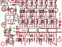
In the picture above, is the LVC on the BMS board the labelled "LVC Test" hole, or the other hole right below it?
 
Thanks, and please keep this up! This is helping me be a little less intimidated about ordering and building my own.
 
The brake switch wires go to the pads labeled BRK and GND shown below.
The LVC test pads, when shorted, activate one of the optos to test the LVC.
In practice, you would run the motor (wheel up or drive disconnected) and short the LVC test pads to verify that it stops the motor. The test function is really just for setup.
ver 2_2 LVC connection.jpg
 
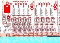
BTW, here is a nicer diagram to assist with placing the parts on the board
(click on the picture to enlarge). Download and print.
This diagram only shows the top side traces and the part outlines (like what you actually see when you're stuffing parts).
Once you figure out where the parts go on one channel, then it's repeat, repeat, repeat...ver 2_2 parts layout.jpg
 
^^^ I found that in the BMS thread, and already saved, and printed out a big copy. It sits on my workbench next to my soldering iron. :D

BRK and GND leads to 10 and 3 on the schematic.

I got it all figured out. Well, at least for now. :wink:
 
As a genuine newbie to circuit board kits I noticed a few things while installing all those minature parts.
anode = positve
cathode = negative
if the hole on the pcb is square well that`s negative
on diodes the stripe is the negative end
soldering happens on the backside of the board
buy a solder station kit with a few tips small diameter solder and a solder sucker

order a few extra parts local stores will not have this stuff

during the destructive testing phase i`ve blown up half a dozen Q101`s and other assorted gizmos due to
a few bms pack leads criss crossed.
Parts are on order/ waiting on shipping.
 
^^^ I have no solder sucker. :(

I just have some fine solder, and a good tip, so after soldering a few resistors now, I have gotten good enough to prevent any spill over to other connections.

One thing I noticed. I don't always get a full load of solder into the hole. I get enough to get good contact on the backside with no gaps, but not enough to fully fill the hole out the front where the resistors are. I assume this is no big deal?
 
I used the sucker to clean out holes on the board after removing some parts. Otherwise it`s mostly useless.

A friend who works on boards wasn`t too worried about getting the hole fully oozing solder on both sides. His opinion about my project.

Even after blasting a few parts with extra volts some channels did appear to work. Good sign. Good Luck
 
Patriot said:
One thing I noticed. I don't always get a full load of solder into the hole. I get enough to get good contact on the backside with no gaps, but not enough to fully fill the hole out the front where the resistors are. I assume this is no big deal?

That's not a problem. As long as you get a good joint on one side it will be OK. The holes are plated through.

Solder suckers are good if you make a mistake.
Another option is SolderWick, which just looks like braided copper wire. You put it down on the joint and heat with the iron and the wick sucks the solder out of the hole by capillary action.
 
So what are your impressions with the ease of building the pack? Are you finding it finicky or tedious? I'm really on the fence right now and am looking for something to tip me over.

Also pics of the build are always appreciated! :D
 
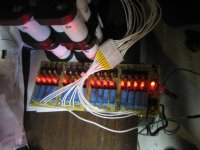
Ok, here's a couple pics of my progress. I haven't gotten too far because I'm taking my time. I also just got an email from Mouser, saying that I won't get the rest of my resistors until March. :(

What the heck!!! Don't they understand this is a project of the utmost importance?

Ah well, I guess I can start doing some more soldering and wiring up of my battery, controller, motor, throttle, regen, etc. That'll keep me busy... for a little while.

DSC01671.jpg


DSC01675.jpg


I'll have to update my Ebike build thread as well. :mrgreen:
 
Back
Top