C Cab Hot Rod Power Advice

Back on topic, one thing to beware of when you try testing the motors is depending on where you got the controller from, the wire colors on the motor may not match the wire colors on the controller. It seems there is no standard for this and is chosen randomly by manufacturers. If the wiring colors are off, what will happen is the motor will do one of several things; not start, start but run rough, or run in reverse. If it's in the 'run rough' or not start configuration, the controller may be pulling excessively high current and could be damaged if you give it full throttle.

Of course you want one motor to run backward, which it can do but the wire colors need to be re-mapped.

The best thing when testing is to have some way to measure the current, like an ammeter. When the motor is wired properly, it will start from any position, run smooth and draw something like 5A for your motors at full speed with no load. 5A is a wild guess, but for that size motor should be in the ballpark.
 
Point taken and duly noted.

I got the converter today and will show wiring progress later.

While I was day dreaming about how this thing will work, 'drive ability', I remembered the subject of using a freewheel had been mentioned. It crossed my mind again, and I have to ask a question.

I believe that when there's no throttle, there is no power forward. The vehicle will just come to a stop, either brake assisted, or it falls of the edge of the flat earth.. :lol:

Using the flat earth scenario, if able to slow to a stop, before plummeting to no where, the motor is still turning, mechanically.

Finally...the question

While this is, 'direct drive' at the moment, is there any chance of damaging the motor/s from repetitive drag, on the motor?

As I had mentioned, one of our parade routes, is mostly down grade. Shouldn't need much if any power for much of the route. Therefore, the motor will be under constant drag, for about a mile or so.

Maybe I should think about adding that freewheel.
 
Hillhater said:
You wont hurt the motors, ....but you may want to reconsider that regenerative charging option ?

Thanks hillhater.
I will look into that regenerative option, as I know very little about it.
Though I'm thinking that my real world use, of maybe 4 or 5 miles, probably doesn't warrant it.
Now if I get it registered, for use on the local roads, then maybe it would be useful.
 
I'm working on a diagram for the accessories, lights, horn, audio etc.

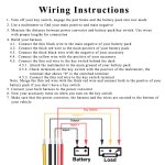
This first diagram is basic as I understand the instructions below.


I'm a bit confused on the switch connection.

Won't I need to use a terminal block, to connect all the various accessories.
Something like this?
https://www.amazon.com/dp/B076BR7RSH/ref=sspa_dk_detail_3?pd_rd_i=B076BR7RSH&pd_rd_w=6M3vp&pf_rd_p=45a72588-80f7-4414-9851-786f6c16d42b&pd_rd_wg=Kh9EN&pf_rd_r=A9WXFDSAV3VDX08TFMX7&pd_rd_r=34fbb213-4b3d-43aa-b972-895098273161&spLa=ZW5jcnlwdGVkUXVhbGlmaWVyPUFXTFJQSzhGOFRKVkwmZW5jcnlwdGVkSWQ9QTA3ODczOTdKV1NPVE41MFk4MTMmZW5jcnlwdGVkQWRJZD1BMDc1MTk0NTI3OFFEUDhSVzc4TUYmd2lkZ2V0TmFtZT1zcF9kZXRhaWwmYWN0aW9uPWNsaWNrUmVkaXJlY3QmZG9Ob3RMb2dDbGljaz10cnVl&th=1

Should the thin red line (?) go between the terminal block, (positive) and the converter?
I plan on using a separate toggle switch, (for each of the accessories) in place of a key switch.
The diagram below only shows head and tail lights as an illustration.


EDIT UPDATE. Hard to read, but I wanted to stay with the wire colors, from the converter.
Need to wire so the 'key switch' from the controller sends power to all systems


And then there is this.

One thing to note: I assume this converter is NOT isolated, which means the main battery will be connected to one of the output wires. As a result, I recommend NOT using the vehicle frame for running power. Run pairs of wires to the lights, etc. and leave the frame isolated. This provides additional safety in the event a wire makes contact with the frame accidentally.
 
Tidying Up

Had to replenish my stores of electrical bits and pieces.
Had a HF 30% off, so made a dash down there and stocked up.
Even bought a new crimper/stripper. My old one must be at least 40 years old.


Put to use some grommets and cable clamps. I like to keep as much tidy as can be.


Found out there is just enough room between the battery and the 'fire wall', for the converter and terminal blocks.
Just need to buy some more terminal blocks. I'm thinking, I will order those I mentioned in my previous post.

I will need to buy about 6' of 8 AWG, to make a cable from the control terminal blocks, forward to the converter terminal block.
Still more finish welding to be done.
 
OK, still struggling with the schematic, but have been looking into
fuse blocks, relay's and dash switches.

It's been kind of cool and windy, of late, so little has been done.

I have been looking and learning, about what fuse blocks are out there, and relay's as well.
They look to be what is needed.

Something like this.
https://www.ebay.com/itm/6-Way-12V-24V-Car-Power-Distribution-Blade-Fuse-Holder-Box-Block-Panel-w-Fuses/293127925644?_trkparms=aid=555018&algo=PL.SIM&ao=2&asc=225074&meid=a0929816d7684f6381fe0b282070b9a7&pid=100677&rk=1&rkt=30&mehot=pp&sd=333238901117&itm=293127925644&pmt=1&noa=0&pg=2386202&algv=SimplAMLv5PairwiseWeb&_trksid=p2386202.c100677.m4598

Or maybe like this...
https://www.ebay.com/itm/6PCS-12V-4-Pin-For-Bosch-Car-Relay-Switch-Harness-Set-30AMP-Fuse-16AWG-Hot-Wire/293174803763?hash=item4442947d33:g:elwAAOSw8EhdQ8iv

AND! If not to make it more confusing, this
https://www.ebay.com/itm/5-Gang-Green-ON-OFF-Toggle-Switch-Panel-2USB-12V-Car-Boat-Marine-RV-Truck-Camper/223140894014?_trkparms=aid=111001&algo=REC.SEED&ao=1&asc=225074&meid=be64d37312b24409ae26e0f1710eb424&pid=100667&rk=7&rkt=8&mehot=pp&sd=113751349135&itm=223140894014&pmt=1&noa=1&pg=2334524&_trksid=p2334524.c100667.m2042

I won't try to show the progress, (or lack of) on another schematic.
I get a little confused, just trying to keep all the lines straight.

After this post, I'm going looking for info on 'how many', (if any), relay's I should use, and how to determine that.

I got the wire, for the power leads from the controllers, to the converter.
Had to settle for #10 awg wire, which I'm sure will be quite satisfactory. It's only 3.5 feet long.
Terminal ends for #8 awg , at my local H.I.S, were over $7.00 USD, and I needed 4.....NOT happening!

I hope to have a clear schematic up soon, for feedback.
 
The first fuse block looks good. The third one has a switch for "Alien lights" so that looks good too. :wink:

10ga. will be fine.
 
I've put in the hours, and worked my brain cells, to the max.

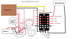
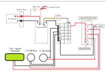
This is what I have come up with, just for the accessories.
Not all lights/accessories drawn in, for clarity.
Obviously I'm hoping that it is correct, but if not, more to learn.

converter - fuse - relay.png

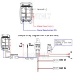
Added for reference

71dZXeYfMML._SL1442_.jpg5 gang schematic.jpg
 
Something doesn't look quite right about the converter wiring diagram. In the text, it says to tie the small red wire to the fat red wire if you don't have a switch, but the diagram shows it going to the 12v output (I suspect this is wrong).

Use an ohmmeter and measure between the converter input and output wires. See if the negative wires are connected internally or if the positive wires are connected. This will clear things up. If the positive input and output are connected internally, then the diagram would make more sense. On mine, the negative wires were connected.

Since the converter has the small red "ignition" wire, you probably don't need a relay. The 12v loads can just come straight off the converter via the fuse block. There will be very little current on the small red wire so you can switch it with a small switch. The converter itself will act like a relay.

Also, I think the switch panel is made for 12v, so that should come off one of the fuses on the fuse block and not connect to the 48v battery.

You can use the big circuit breaker on the battery as the main power switch, but you might want a smaller on/off switch that's easy to reach. You could also use a key switch for this.

If I get time I can do a sample schematic for you.
 
Thanks fechter

I will do the testing as you asked, and get back to you.

I will work up another diagram 'without' the relay, and see if that helps clear anything up.
 
Fechter - tester results

Meter set on 2K

2 blacks --------------------connected (.000)
2 reds ----------------------not connected (no meter reading)

Yellow & Large black ----connected (+/- 375 )
Yellow & Small black ----connected (+/- 375 )

Meter set @ 2000K

Yellow & Red # 1 --------- one connected (+/- 294 @ 2000K)
Yellow & Red # 2---------- Not connected (@ 2000K)
 
I really am trying to get this on my own, but ?
FYI - I'm drawing this using Microsoft Paint, so you could copy it to your PC and modify it at will...I think.

Here is another look. I'm afraid my mind is in stalemate, or is it 'Stall Mate'?
I did notice that there are two sets of red/black wires coming from the back of the switch panel.

Also there is a 'key switch that comes with the motor kit.

Two for the Volt meter/USB/Socket (NC)
Two for the switches. (NO)

Have I created another 'direct short' by attaching the switch positive lead, to the fuse block positive terminal...????????
converter - fuse - no relay.png
 
Yes, yours measures out like mine. Their diagram is wrong. Don't trust it.

Sorry it takes me long to draw stuff.

Basically, your main + and - from the battery branch out on terminal block and go straight to both controllers and the dc-dc converter input. The small red wires from both controllers and the dc-dc can all tie together and get switched to the B+ to turn everything on. This would be the main ignition switch, which could be a key or normal switch.

Everything 12v comes off the converter. Optional whether you want the switch panel to operate the 12v loads (seems like a good idea). Most of these 12v converters will have some sort of short circuit protection so the 12v fuses may be redundant but won't hurt.

You don't want any connection from the 48v stuff to the 12v stuff other than the ground.
 
fechter said:
Yes, yours measures out like mine. Their diagram is wrong. Don't trust it.

Sorry it takes me long to draw stuff.

Basically, your main + and - from the battery branch out on terminal block and go straight to both controllers and the dc-dc converter input. The small red wires from both controllers and the dc-dc can all tie together and get switched to the B+ to turn everything on. This would be the main ignition switch, which could be a key or normal switch.

Everything 12v comes off the converter. Optional whether you want the switch panel to operate the 12v loads (seems like a good idea). Most of these 12v converters will have some sort of short circuit protection so the 12v fuses may be redundant but won't hurt.

You don't want any connection from the 48v stuff to the 12v stuff other than the ground.

Ok Great, I think I understand.

I planned on keeping the two system separate.
But I think our posts crossed, so I'm still concerned that I drew out the diagram correctly.

Please check my last post/diagram.
 
There's a negative wire going from the switch panel to the terminal block. I think the switch panel is all 12v, so best to bring the negative over from the fuse block but I suppose either way could work.
 
fechter said:
There's a negative wire going from the switch panel to the terminal block. I think the switch panel is all 12v, so best to bring the negative over from the fuse block but I suppose either way could work.

I can do that. Actually, that would leave the remaining three B+ and two B- wires, which could be wire nutted together, which probably isn't the better method. At least temporarily, until I get another terminal block.

You haven't directly said anything about the switch panel wires to the fuse block, other than the one negative wire, you just mentioned.
So I'm thinking everything is connected right. Though I'm not seeing the 'switching action' with, where they are connected. I will keep studying it, and maybe it will 'switch on' in my brain.

Thanks for your help and guidance. It means a great deal, to me, and to the success of this project, not to mention the fun and, oh yeah, the learning too.
 
fechter said:
What do you want the switch panel to do?

The original idea was to be able to 'switch on/off, each of the load accessories separately. In this case using an 8-gang fuse block.

If it were just one function that needed to be switched, I would probably see what needed to be done. But this multiple setup, (multi switch-multi fuse block), is what has me flustered. At least this switch panel has all the switches pre-wired, so the only wires to work with, are the 2 power leads for the switches, and the 2 power leads for the three other functions.

I was planning for any future added loads. However, the only accessory, that I can think of, that 'really' needs to be on a switch, is the running lights, head/tail. The switch panel, and fuse panel, I used in my drawing is probably overkill, and could be downsized somewhat.

For example;

the volt meter used in this particular panel only meters 12v-24v. (So it will need to be replaced by a suitable one)

The USB slots, are neat to have in today's 'needs. but not absolute.
Same for the cigarette lighter, power socket.
Though they may come in useful for parade use.(Holiday lights etc.)

Actually this has made me think, that if I use either of the two power points, USB/12v socket, they should be switched as well. Otherwise there would be unnecessary drain on the battery, when not actually required.

At present, these three functions are hard wired, so not part of the 'switching' issue.

The key switch, (from motor kit) could fit in where the volt meter is, thus making use of that space.

That's all I can think of at the moment fechter, hope this gives you a sense of what I'm trying to accomplish.
 
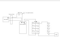
You have a lot of options about how to wire the switches and fuses. Below is just a suggestion but you may have other ideas about what you want the switches to do. Sorry for the crudeness of the drawing.

C-cab schematic 1.jpg

The switch labeled Ignition would be your main on/off for normal use. You could use a key switch for this if desired. This switch doesn't need to be high current. The two controller ignition lines and the DC-DC skinny red would go to this switch. When the ignition is on, the controllers and dc-dc will power up.

The switch panel has only one input, so only one fuse is needed for that. You can run lights, accessories or whatever you want to the switches. You could probably get away without using the fuse block but if you have room it won't hurt. You could possibly rewire the switch panel so each switch goes to its own fuse but that would probably be overkill. Each switch has a quick disconnect feeding it, so you could pull those off and run separate wires to the fuse block for each switch but you'd need to crimp new quick disconnect terminals.

You will need a lot of spots to attach the negative wires from all the loads. The fuse block has this provision.
 
Thanks so much fechter, for taking the time to draw that out.

I think I understand your drawing, so all that remains, is for me to decide what my final components will be, and then apply what you have done, and what I have done, into something that will work.

Another understanding I have is;
for my particular loads, I really don't need to fuse each function. One for the 'block' will suffice.
In either case I'm going to need another terminal block, for the converter/accessory functions.

Thank you again, we're making headway, in educating me, and progress for the project.
 
Just_Ed said:
Another understanding I have is;
for my particular loads, I really don't need to fuse each function. One for the 'block' will suffice.
In either case I'm going to need another terminal block, for the converter/accessory functions.

Right. A single fuse for the whole 12v load side is probably enough.

Afterthought: It would probably be a good idea to have some kind of fuse on the +48v side of the converter in case it decides to short out. 12v automotive style fuses may or may not work properly at 48v though. The fuse will blow at the right current, but may draw an arc between the ends of the fuse wire and turn into an arc welder. Sounds like a great Mythbuster style experiment to do someday (with video!). As long as the fuse is located somewhere that a sustained arc won't set the whole car on fire it should be better than no fuse. You have a circuit breaker on the battery that would be a backup to everything else.

They do make 48vdc rated fuses, but they are too expensive.
 
Schematic Update

OK, here is a consolidation of what you did for me, and whats in my head.
I did away with the fused block, and returned to a basic one. (6 position)
Added a 30 amp fuse to the positive side going to the switch panel. Not sure if it's really needed.
Wired each of the 3 other functions to individual switches.
If I buy a 5-gang switch panel, I'll have one extra switch, for what ever, in the future.

I think (I) understand both as one. I'm sure you will.

fechter diagram - 2.png

I will look into the additional fuse for the 48V side, but now I have some house maintenance to do.
 
That's looking good now. :thumb: Always leave a provision for future additions.

I really think your car is going to need "Alien Lights". My son gave me some LED light strips a while back that I'm reminded of when I saw the alien lights thing. These peel-and-stick LED strips run off 12v and have a programmable remote that can do all sorts of color change, strobing, chasing, etc. Great for mounting on the bottom of the car for ground effect lighting.

And don't forget the laser weapons:
https://youtu.be/FsBR3ZyX_YI
But that's only about 5w. I have a 40w CO2 that runs off 48v. :twisted:
 
Back
Top