C Cab Hot Rod Power Advice

But what I'm confused about is, why it..listen closely...'Screeeeeeched' only when connected through to the motors.
The battery displays 57.1 volts, so I can't see why it would all of a sudden show low voltage. (when connected to a load)
well, that's not the way you described the event before. you said:

When I turn off the battery it lets out a loud screeching,(like dragging a metal table across the floor) and the display goes red, and the numbers drop.
with that decription, a low voltage alarm makes perfect sense.

if switching off the battery also disconnects the power meter from the battery, and the alarm is in the meter, then any capacitors in anything connected to the battery (like the controllers) are still connected to the meter (and alarm) once teh battery is switched off.

then the capacitors drain, usually over a few seconds or so. while they drain, the meter and alarm are still powered. so the meter will show the voltage on the capacitors (not the battery, cuz that's disconnected from the meter when switched off), and the alarm will sound, until the capacitors drain far enough that those electronics can't be powered by them anymore, and the display blanks and alarm silences.


under normal conditions, with the batteyr switched on, the alarm will only sound when the battery drops below whatever voltage it's set at. you can determine this without draining the battery to that point by recording another video that does have sound, and switch the battery off, then watch the video in slow motion to see the exact displayed voltage at the instant the sound starts. ;)


Maybe it's a characteristic of this type of battery.
no battery itself makes a screech sound (none should make any sound at all unless they have electronics designed to make alarms or whatever, or a noisy dc-dc of some type built in...but the battery itself would be silent).
 
amberwolf said:
Maybe it's a characteristic of this type of battery.
no battery itself makes a screeching sound (none should make any sound at all unless they have electronics designed to make alarms or whatever, or a noisy dc-dc of some type built in...but the battery itself would be silent).

Who knew? No wonder I can't find the speakers... :lol:

What I meant by the quoted statement was maybe when the 'package' was put together they installed an alarm system, which you have pointed out. It's just that the 'alarm' noise is very 'alarming', and not what I would perceive as being a typical alarm sound. My email to them asked a similar question.

Not knowing the circuitry of controllers, I didn't realize there were capacitors in them. The sound 'drains' off as well. So with all being said, I think you have explained what is happening.

About my camera not recording sound. Not sure why, so now there's another problem to be solved.
 
If it is a voltage alarm, it would stay on if you really had a low voltage situation during use. When you turn the pack off, the voltage drops to zero, but the capacitors in the controllers keep it up long enough to get the chirp.

Sorry to hear about the flooding issues. I'd be glad just to get some rain here.

Once you get back on it, one of the first things I would do is just see if you are getting 5v on either the throttle or hall sensor power lines. If the 5v is not there, that would be the first thing to track down.
 
fechter said:
If it is a voltage alarm, it would stay on if you really had a low voltage situation during use. When you turn the pack off, the voltage drops to zero, but the capacitors in the controllers keep it up long enough to get the chirp.

Sorry to hear about the flooding issues. I'd be glad just to get some rain here.

Once you get back on it, one of the first things I would do is just see if you are getting 5v on either the throttle or hall sensor power lines. If the 5v is not there, that would be the first thing to track down.

I just went through the connections and was able to get the following. (If I did it correctly)

1. Measured for voltage at the terminal blocks......................................57.1v
2. Measured for voltage from controller lead to the switch.......................55.7v
Verified that the switch on/off function is working.
3. Measured for voltage from controller HALL leads
Black test lead to the black wire.... Red 4.6v, Yellow, Green, Blue all @ .....5v
4. Measured for voltage from controller throttle lead ............................. Red 5v, Green -00.0
Still haven't (retried) with the forward/reverse switch connected.
Not sure how to test the HALL leads to the motor.

Hope this helps.
 
Good sign you have 5v on the right lines.

The hall sensor lines going to the motor get tested attached to the controller. Power on, no throttle, you measure each of the hall signal lines while slowly turning the motor by hand. Each one should toggle high/low as the motor turns. I'd be extra careful with your fingers around those chain sprockets in case the motor decides to run.

If you were getting 5v on all of the signal lines when the motor was attached, that's a problem. Make sure the black wire going to the motor halls is zero volts with respect to the main battery negative.
 
fechter said:
Good sign you have 5v on the right lines.

The hall sensor lines going to the motor get tested attached to the controller. Power on, no throttle, you measure each of the hall signal lines while slowly turning the motor by hand. Each one should toggle high/low as the motor turns. I'd be extra careful with your fingers around those chain sprockets in case the motor decides to run.

If you were getting 5v on all of the signal lines when the motor was attached, that's a problem. Make sure the black wire going to the motor halls is zero volts with respect to the main battery negative.

Super! I will be removing the sprockets/chains to do the test.

Make sure the black wire going to the motor halls is zero volts with respect to the main battery negative.
Do I do that with black lead on the hall connector and red on the positive at the terminal block?
 
FOUND IT!

While trying to figure out how to make connections to check the hall wiring to the motor, I re-checked the voltage to the wires going to the motors. All were at 57.1
So I figured the power is there.

Then I remembered I hadn't yet retried the forward/reverse switch,

So I hooked up the reverse switch, and BINGO !
Houston, all systems are, go for prelaunch systems check.

So with that solved, it's on to finishing the temp wiring for a full-on motor run check.

Thanks for the guidance, that got me this far.
I'm much relieved.
 
I went back out, to sorta recheck, and make sure everything was as I said.

And for the most part, that is still true.

But now, (there's always a 'but') the passenger side motor, is running rough and the wires seem a little warm. Also, it stops and won't restart. So if I've learned anything, the problem has something to do with the hall sensors....right?

When I discovered the power problem, this motor is the one I was using. I thought maybe it was because it needed tightening down, but not the case.

Not sure why the warm wires, for such short spurts of energizing the motors.

I'm sure I remember one of you gentleman making comment,
as what to do in the event this was to happen.


I searched back as far as getting the battery but didn't see it.
I know it's there somewhere, and I guess it needs repeating.

The other motor purr's like a kitten, in both directions.

Edit Update:

I'm not running both motors at once.
 
fechter said:
Back on topic, one thing to beware of when you try testing the motors is depending on where you got the controller from, the wire colors on the motor may not match the wire colors on the controller. It seems there is no standard for this and is chosen randomly by manufacturers. If the wiring colors are off, what will happen is the motor will do one of several things; not start, start but run rough, or run in reverse. If it's in the 'run rough' or not start configuration, the controller may be pulling excessively high current and could be damaged if you give it full throttle.

Of course you want one motor to run backward, which it can do but the wire colors need to be re-mapped.

The best thing when testing is to have some way to measure the current, like an ammeter. When the motor is wired properly, it will start from any position, run smooth and draw something like 5A for your motors at full speed with no load. 5A is a wild guess, but for that size motor should be in the ballpark.

OK, new glasses have been ordered.

This motor is the one that is to run in the forward direction. The rough but short running is in both directions.
Wires on the left are from the passenger motor.

Whoa nellie. Just saw that the wires on this motor are NOT correct. At least in this picture. I'm on my way to verify them now.

DSCN4370.JPG
 
OK, all wiring was checked, rechecked and rearranged as needed.

No apparent damage.

A function check of each motor has been performed, and both are running strong, quiet-ish, smooth and in the right direction. No sense of overheating in the wiring or motors, though they weren't run for any extensive time.

Ran the motors using, the hand throttle, and foot throttle with both working .

Now I need to plan out how to make good connections, where the leads from the two motors must be joined.
 
Good news.

Can you tell if the motors reach the same top speed in forward vs. reverse? With some controllers, it will be the same, with some it may be much slower in reverse.

The warm wires were indicating a very high current. Luckily the controllers were able to self-limit to avoid blowing (they are supposed to do this). Having a current measurement on the battery would be very helpful. At some point I would highly recommend some kind of meter that measures battery current and voltage.

At some point, measure the continuity between the brake wires and the battery + and - (no power). I suspect some of the wires tie to either ground or B+, but we should see which ones. The other test is to power up the controllers and measure the voltages on the brake wires. The brake input is optional, but a really good safety feature.

You might try playing with the 2-speed switch to see what it does. There may be times when a slow speed may be useful.
 
Wiring Update

It's a good thing, (and one reason why) I take pictures. Lots and lots of pictures.
Not only for posting, but as a reference for myself, during the course of my builds.

In this case, it was instrumental in discovering that when I changed to the new terminal blocks,
I didn't pay attention well enough to, where I replaced the wires.

In addition to that, I noticed that the orientation of the motors, (sprocket right & left) and the corresponding hall wiring needed to be swapped. Not that it would have been a problem, but it wasn't as it should be. So I had to swap the wires to the hall wire connectors, so they now match up with the correct motor.
Because I have two motors, both of the referenced connections are required.

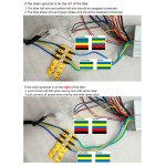
controller wiring photo.jpg

fechter said:
Good news.

Can you tell if the motors reach the same top speed in forward vs. reverse? With some controllers, it will be the same, with some it may be much slower in reverse.

The warm wires were indicating a very high current. Luckily the controllers were able to self-limit to avoid blowing (they are supposed to do this). Having a current measurement on the battery would be very helpful. At some point, I would highly recommend some kind of meter that measures battery current and voltage.

At some point, measure the continuity between the brake wires and the battery + and - (no power). I suspect some of the wires tie to either ground or B+, but we should see which ones. The other test is to power up the controllers and measure the voltages on the brake wires. The brake input is optional, but a really good safety feature.

You might try playing with the 2-speed switch to see what it does. There may be times when a slow speed may be useful.

The motors go full tilt in both directions
I'll have a go at making those measurements, and get back to you.

Not sure how this function should work.
Does it just make the motor run at a slower rpm?
Is it controlled simply by a toggle on/off switch?
Just so happens I have a spare switch.
If so, that would be good to know, as it relates to gearing and road speed...I think.
Exactly how should I 'play' with the 2-speed switch? (I have no such switch)
 
Your hall and phase wiring looks good. Lots of people get stuck on that step or blow something up.

Most controllers have a "3 speed" switch, but I guess yours is only 2. Just a simple switch. It should change the top speed. On the fancier controllers, you can program each speed as desired. On a bike, these are sometimes called a "dork switch" for when you let somebody you don't trust go for a test ride. It minimizes the damage potential. You can also use it the other way as a "turbo boost" switch.

I saw your other topic with the flood pictures. I could use some of that up here (well, not the flooding part). You next project might need to be a boat if it keeps up.
 
fechter said:
Your hall and phase wiring looks good. Lots of people get stuck on that step or blow something up.
The wiring in the 'reference photo', isn't my wiring, just in case, you thought it was.
But I can take credit for it if you insist... :lol:

Most controllers have a "3 speed" switch, but I guess yours is only 2. Just a simple switch. It should change the top speed. On the fancier controllers, you can program each speed as desired. On a bike, these are sometimes called a "dork switch" for when you let somebody you don't trust go for a test ride. It minimizes the damage potential. You can also use it the other way as a "turbo boost" switch.

Turbo boost. I will remember that, and use the designation for another 'show detail'. :D

So if I get what you are saying, the motor doesn't have to be a 'designated' 2-speed motor?
To use that function, would take a SPDT switch ? Switching between 'high' and 'low' so to speak.
Or does it only take a simple on/off switch to do the trick?

I saw your other topic with the flood pictures. I could use some of that up here (well, not the flooding part). You next project might need to be a boat if it keeps up.

I'll get started on the channel up to your area. Oh! that's right, water doesn't naturally flow uphill. Sorry :(
 
Today I've been working on a mock-up, battery cover/console.
Not what I had in mind, when originally designing, this car.
But the design has to evolve as the need arises.

This is but the first design and the most practical.
It's quite boxy, so it needs some contrasting pockets, holes, do-dads.....you get the idea.
I'm initially thinking of upholstering the sides with a contrasting tan fabric.
Or red sides, and wood grain in the center.
May even make it out of metal.
I will dwell on the design in hopes of fancying it up somewhat.


Three different heights.
There's not much room under the top, where it turns vertical.


Moved the voltage gauge to the front.

 
Looking good. I love CAD (cardboard aided design).

The speed switch works with any kind of motor. It simply limits the throttle. You can use a jumper wire or short the speed switch wires with a screwdriver to see what it does. It might be interesting to see what happens if you only slow down one motor. This could be helpful in a hard turn.
 
fechter said:
Looking good. I love CAD (cardboard aided design).

The speed switch works with any kind of motor. It simply limits the throttle. You can use a jumper wire or short the speed switch wires with a screwdriver to see what it does. It might be interesting to see what happens if you only slow down one motor. This could be helpful in a hard turn.

Ok ... Noted!

Another CAD mock-up. I'm liking this version a bit better.

But I'm waiting for the creative juices, to flow (wait, not 'flow'), to bring me other ideas.


fechter said:
It might be interesting to see what happens if you only slow down one motor. This could be helpful in a hard turn.
now that's something clever i never thought of. :oops: :!:

and easy to setup for automatic operation with microswitches on the steering, operated by cams.
 
amberwolf said:
fechter said:
It might be interesting to see what happens if you only slow down one motor. This could be helpful in a hard turn.
now that's something clever i never thought of. :oops: :!:

and easy to setup for automatic operation with microswitches on the steering, operated by cams.

I think tanks and bulldozers work that way don't they?
Am I going to have to change the wheels and tires, to wheels and tracks?
 
Just_Ed said:
I think tanks and bulldozers work that way don't they?
not exactly. depending on the system those can have independent power controls for each side, which is a different thing than what i'm talking about.

what i'm talking about is an automatic system built into the steering wheel or yoke or whatever is used, that has a pair of cams on the main tube at the center of that wheel or yoke that rotates as you turn. each cam is angled opposite to the other, and a pair of microswitches rides at the "top dead center" of that tube, on the cams, so that when its' centered the speed switches are both in the same position. then as you turn the steering wheel / yoke one direction, the tube turns and the cams push one switch to it's other position, and hold the other switch in the same position. the opposite happens when turnign the wheel/yoke in the other direction.

so, depending on how you want to run the system, the default position / speed could be the low speed, then turning gives a boost of speed on the outer motor, leaving the inner one at the low speed. or the default could be the high speed, and turning cuts the speed on the inner motor, leaving the outer one at the high speed. (the latter is probably better, since you generally don't want to speed up in a turn)


fwiw, i have used independent throttles for the sb cruiser's motors, and it works pretty well, but with my random hand numbness, it's grown impractical becuase i might be unable to use one or the other throttle (sometimes both) effectively, for a few minutes at a time, randomly, and thus lose half (or all) of the motor power.

so now i use parallel throttles, plus pedal control (throttle overrides pedals), so any of the three can give some or all of the whole system's motor power at any time. but i would really like to have the ability to push thru a turn with more power on the outer motor and less on the inner, which is why i commented on fechter's idea. ;)


either way, none of these systems require changing anything about the way the hot rod is built.

you would only need to change to tracks if you needed the terrain-handling abilities those provide over wheels. that's pretty unlikely from the descriptions youv'e given of this vehicle's purposes.
 
Zero turn, front wheels 90 deg capable. will need a separate reverse switch for each motor. then you could just spin in circles. just kidding.

Think they have touched on this early in this thread.
 
amberwolf/ZeroEm, there must be a very impractical but really fun build in there someplace.
 
Your doing the fun build. You can finish with nothing fancy, then later play with motor steering later.
Like AWD you can track wheel speed of each wheel and control the traction, turning and braking.

EV's are never done, always a work in progress.

I still need to put a switch so I can have reverse.
 
Just_Ed said:
I think tanks and bulldozers work that way don't they?...
Systems vary...but in its general form, Tanks, ‘Dozers, even most Ag tractors, have differential axles and simply use independent brake controls on each wheel..leaving the ‘Differential to split speed and Torque distribution.
( Ag tractors simply have 2 brake pedals ..very effective)
Common examples in daily use are “Zero Turn” mowers (mechanical), and Electric wheelchairs with J’stick control
However modern systems using independent Hydraulic or Electric traction drive, use more complex control systems.
In its ultimate form on electric drive systems with individual traction motors , it is known as “Torque Vectoring”.
A fancy tech’y name, but basicly the same effect as AW suggested.
However, i doubt you need such extra complication on your parade cruiser !
:bigthumb:
 
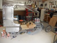
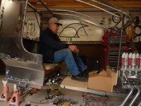
I needed to see what the new console looked like with the body on.
Also how much legroom, remained with this design.

Also, worked on the visibility problem. Between my height and how the top is designed, I couldn't see straight out the front.
These pictures don't show the change, but with fiddling with the angle of the dangle, I settled on raising the front, two inches, which makes very little change in the overall appearance of the car. I lowered the seat height to its finished height +/-. It will also give me an attaching point for the required rearview mirror, and wiper motor. I wonder if I can get away with using a hand-operated wiper. I see a lot of them for sale. Maybe not legal for the street. I haven't checked yet.

DSCN4394.JPG

The verdict is still out whether to use the 5-gang switch panel. I'm not sure what it is,
but my gut tells me it isn't right. Maybe something else should be used.

DSCN4397.JPG

This type of 'hot rod' isn't made for creature comfort. But I'm not really uncomfortable,
though I'm seeing more of my knees than I would normally like. :lol:

Also, the time is near to think about installing the steering column/wheel.
Will probably use a removable steering wheel and/or a tilting column.

DSCN4398.JPG

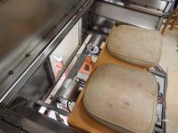
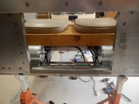
As you can see in the next two pictures, there's little room, in the motor compartment.

DSCN4399.JPG
DSCN4401.JPG
 
Back
Top