
You are using an out of date browser. It may not display this or other websites correctly.
You should upgrade or use an alternative browser.
You should upgrade or use an alternative browser.
Can somebody help me with wiring 36 to 6volt module Vogue (60-4-b)
- Thread starter chibenzo
- Start date


Do you have a link to the page where it was purchased? (there is often info on these pages that may help us help you)
If it wasn't purchased separately, but came with something else, a link to the page that something else was purchased from could be helpful.
More information about how you are trying to use it, and what you are trying to connect it to, would also be helpful.
If it wasn't purchased separately, but came with something else, a link to the page that something else was purchased from could be helpful.
More information about how you are trying to use it, and what you are trying to connect it to, would also be helpful.
Chalo
100 TW
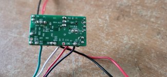
You didn't supply a picture of where the wires attach to the PCB.
36V, 6V, GND (ground), and SW (switch, probably) are all clearly marked on the PCB. Is that not enough to get you where you're going? It is a little fishy that the GND pads don't seem to have anything soldered to them.
If it helps, those plugs are JST-SM 2-pin female, 3-pin male, and 4-pin male. So if you want to plug into them, you'll need a 2 pin male, and one each of 3 and 4 pin female plugs.


There is onley 1 that i found DC licht module Vogue (60-4-b)Do you have a link to the page where it was purchased? (there is often info on these pages that may help us help you)
If it wasn't purchased separately, but came with something else, a link to the page that something else was purchased from could be helpful.
More information about how you are trying to use it, and what you are trying to connect it to, would also be helpful.
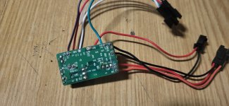
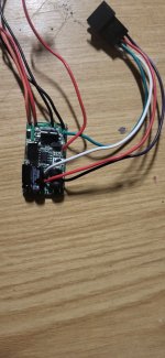
@ChaloOk r these pica good?
You didn't supply a picture of where the wires attach to the PCB.
36V, 6V, GND (ground), and SW (switch, probably) are all clearly marked on the PCB. Is that not enough to get you where you're going? It is a little fishy that the GND pads don't seem to have anything soldered to them.
If it helps, those plugs are JST-SM 2-pin female, 3-pin male, and 4-pin male. So if you want to plug into them, you'll need a 2 pin male, and one each of 3 and 4 pin female plugs.
Attachments
marty
10 MW
No not good. Can you make a drawing showing 3 connectors, Wire colors, and which wire is connected to what marking on circuit board.Ok r these pica good?
Chalo
100 TW
Yes. If 6V doesn't show up automatically on the 4 pin plug, I'd join across two pins on the 3 pin plug (after measuring them both against black to make sure they're lower than 36V-- like somewhere in the 5V to 12V range. If the orange wire shows a voltage relative to black, I'd join those two. If it shows no voltage or only millivolts relative to black, I'd join red to orange. Whichever combination makes the 6V wires turn on in the 4 pin plug would be the enable switch.Looks like you just need to connect the battery positive and ground to the two pin connector (red and black), then you can measure the outputs on the other connectors with a voltmeter.
If there's support for a brake light here, then it gets more complicated to figure out.
Thank you for responding, I have tried this method and measured it with a multimeter, but there was no voltage on any pin other than the 36V pin.Yes. If 6V doesn't show up automatically on the 4 pin plug, I'd join across two pins on the 3 pin plug (after measuring them both against black to make sure they're lower than 36V-- like somewhere in the 5V to 12V range. If the orange wire shows a voltage relative to black, I'd join those two. If it shows no voltage or only millivolts relative to black, I'd join red to orange. Whichever combination makes the 6V wires turn on in the 4 pin plug would be the enable switch.
If there's support for a brake light here, then it gets more complicated to figure out.
docw009
10 MW
Did you attach a switch to the switch wires?Thank you for responding, I have tried this method and measured it with a multimeter, but there was no voltage on any pin other than the 36V pin.
If you measure no voltage at the Vcc point, then seems like something is fried, or there’s possibly a bad solder joint. Looking at the pics, is the solder connection for the 36v input solid? I’d wiggle wires around to make sure there’s no bad connections.Thank you for responding, I have tried this method and measured it with a multimeter, but there was no voltage on any pin other than the 36V pin.
Did you look at your controller for corresponding (free) plugs? Is yours a Lishui controller? I have a (bad) lishui controller and it has such sort black box connected to it. On the 4 wire controller female plug; purple, red, green, white. On the controller female 3 wire plug; red, black, orange. These 4 and 3 wire plug connects to the light module with corresponding colors in the correct position. There is another female 3 wire plug on the controller but i guess that's for a cadence sensor (red, black, blue).
Anyway, that purple wire from light module (marked on light module pcb with 6V) go's inside the controller and comes back out (just a loop inside controller) as a single purple wire with a white 2 pin female plug on it from which only the purple wire is in that plug. maybe that is the 6 volt?
On the light module, that 2 pin female connector with black and red wire, on the pcb there seems to be a diode inline so if you feed 36 volt to the 2 pin plug it get blocked. (At least it seems to be on the light module i have).
Best thing to do, check your controller for corresponding plugs, switch the bike on and i don't know your display but check for a light button function and measure on the controller the single purple wire with white connector if you have 6 volt output. But i find it strange if that is the 6 volt out that there is no ground wire in that white plug. But I hope this will get you a little further...
I connected my bad controller anyway and switched it on, on that single purple wire with white plug coming out of the Lishui controller sits 6.2 volt between purple and ground when controller is on. On the light module 2 pin female red and black wire i measured nothing.
thanks for responding I will definitely try these solutions by the weekend and let you know if they work or not grtzI connected my bad controller anyway and switched it on, on that single purple wire with white plug coming out of the Lishui controller sits 6.2 volt between purple and ground when controller is on. On the light module 2 pin female red and black wire i measured nothing.
no i didntDid you attach a switch to the switch wires?
docw009
10 MW
When you give you a switch circuit, I think they expect you to use it,
i tried but had no voltage on purple cable coming from my lishui controllerI connected my bad controller anyway and switched it on, on that single purple wire with white plug coming out of the Lishui controller sits 6.2 volt between purple and ground when controller is on. On the light module 2 pin female red and black wire i measured nothing.
Similar threads
- Replies
- 2
- Views
- 345

- Replies
- 9
- Views
- 1,931