
You are using an out of date browser. It may not display this or other websites correctly.
You should upgrade or use an alternative browser.
You should upgrade or use an alternative browser.
Can someone tell me how to hook the sine wave up
- Thread starter larsen1921
- Start date


Apparently you have something like a wire diagram for this already. Did you buy a matching throttle, ebrake lever, and other pieces that hook into this? if not, it's time to get soldering / putting new connectors on to match your existing controller accessories.
larsen1921
10 W
I need to know what the phase wires are
larsen1921
10 W
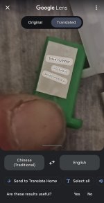
I attached all the wires images that I have that are not the phase wires I already know which one the hall wires are I just can't figure out which one the phase wires are
larsen1921
10 W
And no there is no wiring diagram
floydr
100 W
A photo of the controller might help or link to the controller. As none of the photos showed phase wiring. Does the controller have three bolts mark W,V,U?
larsen1921
10 W
Nope sure don't
larsen1921
10 W
1200W Brushless Sine Wave Motor Controller 48V to 72V Durable for Electric Vehicles Sine Wave Motor Controller https://a.co/d/2QPGzTN

larsen1921
10 W
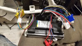
@neptronix is right, pop the plastic up on the left side, by the blue/yellow/green making.Here's the picture
Battery terminals are on the opposite side, under the plastic, red and black marking
larsen1921
10 W
Oh my God you brilliant frockers thank you
larsen1921
10 W
Cuz the face wires was on the other side thank you
larsen1921
10 W
So I still ain't getting no luck on shit....... Y'all thank there's a electric lock thing
Check out this diagram, it's from a similar controller, so the diagram is going to be similar, if not identicalSo I still ain't getting no luck on shit....... Y'all thank there's a electric lock thing

larsen1921
10 W
No orange wires
Sorry, but as you and others on the product review pointed out, there's no wire diagram. You have phase wires, battery, and hall sensor connected. presumably you found throttle as well. You can test different combinations to see if there's an on-off connector, or perhaps a self-learning wire.
Looking at the pictures you supplied, nothing seems to match the description of a function to lock/unlock the motor or turn it on and off.
Unless you're hiding a degree in electrical engineering then playing with random wires to find out what works is going to result in a blown up controller.
You should ask the vendor for details and request a refund if they don't help.
This is all pretty typical for a product from a random Chinese Amazon vendor. I would never advise anyone buy parts from any of them. Many of them know absolutely nothing about what they're selling, so how could their customers?
Found this, it looks the same and has somewhat of a wiring diagram
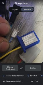
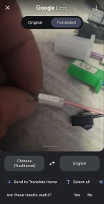
A lot of the cheap controllers (including mine) use a red wire, like the one with the ring terminal, as the electric door lock. On mine, connecting that to battery positive turns on the controller.No orange wires
The two red JST connectors are likely for alarm. Alarm requires power even when the controller is off, so you can test for battery voltage on one of those red wires. If so, that could be where your on/off switch could go, between the batt positive from the alarm power, and the red wire with the ring connector, door lock.
Proceed with caution. This is how it works on a couple of my controllers, but not guaranteed for yours.
slaphappygamer
10 kW
I just wrote what was mentioned by E-HP.  Didnt even realize until I sent my reply. Id go with what he said.
Didnt even realize until I sent my reply. Id go with what he said.larsen1921
10 W
Thank
A lot of the cheap controllers (including mine) use a red wire, like the one with the ring terminal, as the electric door lock. On mine, connecting that to battery positive turns on the controller.
The two red JST connectors are likely for alarm. Alarm requires power even when the controller is off, so you can test for battery voltage on one of those red wires. If so, that could be where your on/off switch could go, between the batt positive from the alarm power, and the red wire with the ring connector, door lock.
Proceed with caution. This is how it works on a couple of my controllers, but not guaranteed for yours.
Bro thank you so much that was the correct diagram man you're frocking awesome
Found this, it looks the same and has somewhat of a wiring diagram
larsen1921
10 W
Thank you also your shit helped out quite a bit as well thank youA lot of the cheap controllers (including mine) use a red wire, like the one with the ring terminal, as the electric door lock. On mine, connecting that to battery positive turns on the controller.
The two red JST connectors are likely for alarm. Alarm requires power even when the controller is off, so you can test for battery voltage on one of those red wires. If so, that could be where your on/off switch could go, between the batt positive from the alarm power, and the red wire with the ring connector, door lock.
Proceed with caution. This is how it works on a couple of my controllers, but not guaranteed for yours.
Similar threads
- Replies
- 2
- Views
- 335
- Replies
- 7
- Views
- 225