Can't get new crystalye 35a controller to work.

Tony

100 mW
Joined
Apr 5, 2007
Messages
47
Location
RI
Switching from the stock 15a controller to the crystalte 35-72v on BMC hub motor and can't get it to work. I've gone through all the troublshooting steps I've found here on the forum but no luck.I may have made a serious mistake when I hooked the old throttle to the new controller incorrectly and blew the throttle, (got a new one now that fits properly)

-got 52v at the battery
-replaced the throttle and it toggles between 4-0 volts
-checked the hall connectors, red+blk=7v, black to each color reads between 0-14v when wheel turned, red to colors reads between 0-7 volts when wheel is spun.
-when all wires hooked up and power on I get resistance when I spin the wheel backwards.
-Ohm test of the motor wires =.1 to .2
- I checked for voltage coming from the controller, 4v between all colors except between blue and green which is 0, I'm not sure if this means anything.
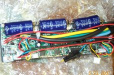
- I opened the case and unpluged the brake inhibit and still no luck
- After I opened the case the power on switch crumbled- Great :(

Is there anything else I can try or did I possibly fry the controller when I hooked the throttle up incorrectly. I would try the old controller but the throttle dosen't match. Thank you.
 
,
red to colors reads between 0-7 volts when wheel is spun.

shouldn't dude :!:

Should be black to each 14V

check out
http://www.crystalyte-europe.com/

scroll down left side to about motor controller/checking halleffect

If you mean the power on led disconected the controller will work without it :!:
If you mean the power on switch connector disconected then repair
 
hi tony,

i dont know a great deal here so i'm just trying to help with the limited knowledge i have so bear with me.
did the motor work with the original controller?
i ask as i have a puma with the crystalyte 36-72v 35a controller too and the phase cables to the motor need swapping - as i say im no expert but im reasonably sure that it wont work unless you swap the phases?
if you take a look at my thread you should find a picture of where my phase from the controller connects to the motor and you'll see that the colours dont match at all lol, its something to do with the puma having the phases wired differently depending on which side of the axel the motor cables come out on or something, the other guys will be able to tell you more (maytag has one and had the same problem so check his thread too).

Hope this helps some mate as the puma at 35a 50v will go like a "mofo".
good luck mate - if you get no joy i will check when i get home and tell you how my colours match up.


Cheers

D
 
Thanks for the responses, the motor worked before with the original controller. I've got a front hub motor so the phase wires should match up color to color- although with the original 15a controller they were not matched up from controller to motor to make things even more confusing. Anyway I hooked the phase wires up both ways, color to colr and the original way- yell to blue, blue to green, green to yellow, see pic and neither way worked. Perhaps I should try another combo?
 

Attachments

  • DCP_2362.JPG
    DCP_2362.JPG
    69.5 KB · Views: 2,268
Hello There

Sometimes you can blow the 5V regulator on the board esp. if you hook the throttle up incorrectly, If you follow fechters brilliant test procedure you should be able to diagnose the problem.
The power on switches are poor quality, make sure you have the LED on, the brake inhibit has to be made to inhibit so that wont be a problem. sometimes the throttle cable wires can burn out
inside, If you have the controller open check for continuity from the controller plug (throttle cable inside the controller) to the plug on the outside, I have seen the wires melt inside these when the
throttle has blown, it can also sometimes cause a full throttle condition.

Check in-between all motor phases, they should all pretty much read a dead short, you can also try this move the wheel backwards a little against the freewheel and then try again to see if it spins
if not move it back a little more and try again, this can sometimes indicate a blown fet that has gone open.

Fechters thread is pretty amazing, follow that come back and let us know.

Cheers

Knoxie
 
It sound like the controller is mostly working.
It's pretty easy to blow a throttle by hooking the +5 to the output by mistake, but it's hard to blow the controller. The +5 output to the throttle is current limited.

It sounds like the halls are connected, but it's possible the colors aren't matched properly. Try putting the wheel up, give a little throttle and spin the wheel backward a bit and see if you can feel it trying to run.

I don't know the color code for the BMC motor. If someone knows what the matchup is, it would be good to post it in the Crystalyte thread.

If everything checks out but it still won't run, it could indicate something less common blew in the controller.
 
OK , I opened the controller to properly check it. The continuity is good from board to throttle on all 4 wires. I did not notice any burned areas anywhere. checked voltage at the board and connections for throttle, blk+ brn=5v, blk + yell 1-4 volts with movement of throttle. I also checked for continuity on the hall wires from controller and thats good. All the hall wires are connected color to color. Still have resistance when I spin the wheel backwards- I also tried spinning the wheel and applying throttle, no luck. Re checked the phase wires into motor as well as the hall signals=good. I guess the next step is to open the motor to see if the hall signals are making it in. I'm also going to get another trottle for the stock controller to see if I can get it to work that way. Any further suggestions? thanks for all the inputs much appreciated. Tony.
 

Attachments

  • DCP_2363.JPG
    DCP_2363.JPG
    98 KB · Views: 2,241
If the hall signals weren't making it in, there would be no resistance to turning backward.

You could measure the hall signals right at the connector on the circuit board if you can power it up and attach the motor.

Possibly a broken resistor in the low voltage cutout circuit?
You could try and measure the voltage on R30.

There's a bunch of other places to check, but it gets complicated.

It sounds related to the throttle or the PWM chip.

Do you have an oscilloscope?
 
Hi all; long time lurker, first time poster. Now that it seems that management here will deal with trolls, I plan to become more active.

I hope I understand the problem correctly. You are trying to connect a Crystalyte controller to a BMC motor, right? Perhaps the three phase power from the controller to the motor isn't connected correctly.

Both controller and motor have blue, green, and yellow wires, but the meaning of those colors aren't quite the same between Crystalyte and BMC.

Maytag has generously posted a wiring diagram:
http://endless-sphere.com/forums/viewtopic.php?t=541&start=8

I followed this and successfully got my BMC motor to work with a Xlyte 20A 36-72V controller. It's basically controller blue to motor yellow, controller yellow to motor green, and controller green to motor blue. Once I verified the Xlyte-BMC combo works, I rewired the motor to match the controller.

Today FedEx delivered to me from DigiKey a dozen IRFB4310 mosfets plus mounting kits with mica insulators. Sometime soon I will replace the controller mosfets and their mountings, but right now I am more concerned with the mosfets in the EVTech lipos:
http://endless-sphere.com/forums/viewtopic.php?t=954

The controller supposedly will work up to 100V, but the battery BMS is proven to fail at 72V.

I sure hope I can finish building my bike this holiday weekend. Then I can post pictures.

Disadvantage
 
I don't have an osiloscope, I measured the voltage across R30=9v (across the outer 2 pins) diden't look like a typical resistor,( black square)- I don't know if that was the right place to measure- right near where R30 is written. I measured the hall wires at the board and they check good.
 
I followed this and successfully got my BMC motor to work with a Xlyte 20A 36-72V controller. It's basically controller blue to motor yellow, controller yellow to motor green, and controller green to motor blue. Once I verified the Xlyte-BMC combo works, I rewired the motor to match the controller.

This set up should be for a rear Puma and I have front- so the phase wires should connect color to color- I tried all combos anyway and it diden't work. I think I'm close to giving up on this. Boy you sure have to be careful with electronics one slip of concentration and kaput.
 
Ok, I hooked the old controller up and spiced in the new throttle (correctly this time)- and everything works well. Soooo theres got to be somthing up with the crystalyte controller- I've gone through Fetchers troubleshooting thread and everything checks out good- so I must have fried the PWM chip when I hooked up the throttle wrong? Although I would think that it very unlikely. Is there anything else I could try before sending it back to powerride store? I talked with Earl and he said he would look at it, seems like a good operation there, he actually answers the phone and is quite pleasant. I hate to send it back as I prob will not get a refund. Any thoughts Thanks again for all the input. Tony.
 
Unless you managed to touch the battery voltage wire to the throttle signal input, I'd claim it as a manufacturing defect or random component failure.


The throttle signal goes through some op-amps before it gets to the PWM chip. Ramp up delay and scaling circuits. Those would be suspect, but would also be a PITA to replace.
 
I have a BMC from EVTech and my Xlyte 36v 20a controller dont work either. I also have a 35A EVtech controler and all works great (when colors are as per Maytag). Put in the Xlyte and nothing; :evil:

Throttle LEDS on.
Roll wheel back and there is resistance.
5V measured going to throttle.
Hmmm

I did notice the BMC will pulse forward if the throttle is plugged in 'hot'. :shock:

I DIDNT short my throttle and had connected everything perfectly to the Xlyte when it was fresh new out ofthe box. So something is screwy here. Any others out there? :x


Tony said:
Ok, I hooked the old controller up and spiced in the new throttle (correctly this time)- and everything works well. Soooo theres got to be somthing up with the crystalyte controller-
Code:
 
Hmmm.... hard to say.

Try giving it some throttle while rotating the wheel backwards (wheel off the ground) and see what happens.

The pulsing when connnecting the throttle might indicate the throttle wiring is not quite right. I wonder if they wire the 20A controller differently?
 
SUCCESS!
Fechter was right. The earth and the 0-4.2v signal wire is wired wrong way around on EVTech thumb throtle versus the XLyte plug. I swapped the wires on the throttle (black and white wires) and now works perfectly. :lol: :p

Incidently, the main motor wires and hall effect wires are all color on color from BMC to Xlyte. NOT as in other posts at least on my rig. (CT3620 Xlyte). Reverse keyswitch is set to green dot (forward?).

Off for a run! Thanks to you guys.


fechter said:
Hmmm.... hard to say.

Try giving it some throttle while rotating the wheel backwards (wheel off the ground) and see what happens.

The pulsing when connnecting the throttle might indicate the throttle wiring is not quite right. I wonder if they wire the 20A controller differently?
 
Yep sure works. 20" wheel 25mph on flat. Fast enough for this bear.
 
Now I really want to get one of those motors :twisted:

When you get a chance, see if you can post the successful arrangement of wire colors.
 
Yes the BMC is a great motor but is not going to take more than 20A without bigger wires. I ran 35A briefly and wires were at melting point in 2 mins. So I am runnung bog standard 36V lipo with xlyte 20a and all is well. I imagine 48V and 35A would put a smile on your face but you will be in the garage for a long while first wiring it up. In any case 25mph at 20a is plenty for me.

Wiring is as follows;

BMC Hub --> Xlyte controller ; ALL Color on Color (for me no change needed)

CT3620 Crystalyte controller throttle plug =
1 Purple= 5V
2 Yellow= Ground
3 Green = 0-4.2V Signal
4 Blue = Battery Volt for LED (in my case LIPO 40V)

EVtech thumb throttle plug =
1 Red = 5V
2 White* = 0-4.2V Signal
3 Black* = Ground
4 Purple = Battry Volt fo LED

*NOTE black and white from EVTech throttle doesnt match the standard Xlyte plug wiring. I swapped black and white on the EVTech throttle and all now works perfectly.

So be careful guys. You cant plug just any throttle into Xlyte as plug wiring may vary on your throttle.
 
lelievre12 said:
Yes the BMC is a great motor but is not going to take more than 20A without bigger wires. I ran 35A briefly and wires were at melting point in 2 mins. So I am runnung bog standard 36V lipo with xlyte 20a and all is well..

What was the battery voltage when the 35A controller was used?

Could your 35A controller be used with your 36V lipo? Have it been tried?
 
I dont have an ammeter on the bike so cant tell you. I guess if its 35amp controler then you would expect 35amps at full throttle! Whatever the numbers it went like a bat out of hell. I never did get a top speed as wires got too hot and I went back to the 20amp controller. The EVTech 36v lipo's delivered 40v the whole time. Unstoppable.

Bad news is today I broke the lead to my throttle and need another. Silly fault where not enough slack at the handlebar.
 
Back
Top