thunderstorm80
1 kW
- Joined
- Mar 29, 2016
- Messages
- 383
Hi,
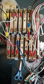
I have a 24S A123 battery I have built myself, by using the common screw metal tabs with M5 screws for fastening.
I attach a picture of a battery during assembly so you can see what I mean.
Since each tab has two screws, then each side of the pack is terminated with two heavy gauge wires, that hold to the M5 screws with ring terminals.
I also hooked up on each of the 25 tabs a smaller ring terminal with a thin wire, and those are leading to four 6S "BMS" terminals.
I noticed that on the extreme cells of the pack, the voltage via that "BMS" terminal is sagging (or rising) during a current load.
The current doesn't pass through the thin BMS wires but through the heavy gauge battery wires.
I suspect that since the current is flowing out/into the battery from two heavy wires and not just one (you can see the black wires which will act as the "-", already assembled), and since the cell tabs which the metal tab is pressed against are not perfect, then there will be some current (even if very small) flowing through the tab itself, creating this voltage sag/rise on the BMS voltage terminal.
Am I correct about this? And if so, what can be done?
I know an immediate solution is to use only one exiting heavy gauge wire (and heavier) which is terminated at the same screw as the BMS terminal, but I fear from focusing 110A of peak current only on one side of the metal tab, which is buried under several layers of insulation with no air flow. (although if everything is hooked properly and securely, this should be ok, but this is a DIY project and I prefer to have safety factors)
I assume a similar problem can occur in a cylinder-cell battery with more than 1 parallel group.