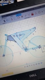
CF or Glass Fiber over PVC Pipe

what about buying prefabricated CF tubes? As far as I remember they are not too expensive. Acounting for materials and labour you might be saving money long-term. Using Balsa or expanded polyurethane as the base is also a good idea, :bigthumb:
 
advancedelectricbikes said:
Fiberglass laid up on a balsa wood dowel core may be a good strength to weight compromise.
craciunptr said:
what about buying prefabricated CF tubes? As far as I remember they are not too expensive. Accounting for materials and labour you might be saving money long-term. Using Balsa or expanded polyurethane as the base is also a good idea, :bigthumb:
Both are valid alternatives.
CF Tubes are expensive in the size and lengths required.They are also round ... although there are some limited sizes of rectangular tubes available.

Balsa can be cut, glued, laminated and sanded to form nearly any shape model required.
It is also relatively inexpensive to work with.

My interest in PVC-pipe as a model material was peaked because it is relatively inexpensive and can be bent to form with the use of a heat gun. I have recently learned of another alternative which is closed cell foam PVC sheets. This relatively inexpensive material can be bent to form with a heat gun and can be cut, glued, laminated and sanded to form much like balsa wood as well. Available in sheet thicknesses of 1/8, 1/4, 1/2 and 3/4 inches. One source for the material is:
http://www.hfmfgcorp.com/closed-cell-expanded-pvc-foam/

They also have a similar material available via retail outlets such as Home Despot under the brand name "Phase-2 PVC Paligh".
Available in sheet thicknesses of 1/16, 1/8, 3/16, 1/4 and 1/2 inches.
http://www.hfmfgcorp.com/phase-2-palight/

I am given to understand these materials are commonly used in model construction, signage as well as theatrical props.

DataSheet: https://www.piedmontplastics.com/resources/literatures/palram-palightR-fabrication-guide
 
For glass fiber there is E-glass and S-glass that are commonly used. E-glass was originally designed for electronic applications (PCB boars, etc), hence the name. It is used because it's cheaper.

S-glass is a high grade of fiberglass. Stronger then carbon fiber.

The advantage to carbon fiber is that it is extremely stiff. Glass is fairly flexible and would require a lot more layers to get as stiff. Although the result would be extremely strong.

I would do foam core instead of PVC pipe. It is a proven approach used in a wide variety of different situations. Experimental aircraft, racing cars, etc. Lots of information, lots of testing, lots of documentation on how to do it right. Also it is important to have nicely radiused connections between the 'tubes'. Fiber layup does not "do" sharp angles. Hard to do and also weak.
 
I'm curious if this project ever progressed into the experimental stage. Any photos to share?

If you check out my signature links, you can see how I pursued a similar path using plywood as a substrate for S-glass and epoxy. I chose plywood in part because I wanted the extra stiffness and partly because I hadn't heard of the neat hot sand trick for shaping PVC. Although, just the other day I was thinking about building a rain dodger and started looking sidelong at a pile of spare PEX plumbing tube . . .

For what it's worth, I'm an epoxy believer due to its superior adhesion. For PVC especially, it seems it would be important to rough up the tube to give the epoxy something to grip onto. I found that a single layer of glass has been adequate to add stiffness, but that might be due to the plywood providing structural strength. I did add a second layer of glass to the critical structural areas like the rear "legs". I also varnished the frame to provide UV protection.

It ain't exactly light, but it's strong, stable, and it gets up to the 1000W motor's top speed plenty fast enough.
 
weezthejuice said:
I'm curious if this project ever progressed into the experimental stage. Any photos to share?
...
It ain't exactly light, but it's strong, stable, and it gets up to the 1000W motor's top speed plenty fast enough.
Negatory. I am not certain I have the space, where-with-all, physical resources or financial ones to even begin it. Still I spent too many years as a designer to not give some practical thought.
 
Another way to go would be to use high density structural foam, carve out your frame then coat with fiberglass cloth and epoxy.
 
I've made my own carbon sandwich bike by 3d printing the cores/mandrels with CF-containing filament (mostly for less CTE and better adhesion than strength per se) and covering it with carbon fiber, and GF fiber in sections where it actually *needed* to be flexy.
DxTgTi4h.jpg

arGljNFh.jpg
 
BalorNG said:
I've made my own carbon sandwich bike by 3d printing the cores/mandrels with CF-containing filament (mostly for less CTE and better adhesion than strength per se) and covering it with carbon fiber, and GF fiber in sections where it actually *needed* to be flexy.
DxTgTi4h.jpg

arGljNFh.jpg

Balor, interesting comment using CF containing filament in 3D printer. Did you 3D print the headtube mandrel? Are you using it as an integrated headset arrangement to drop the bearings in?
 
BalorNG said:
I've made my own carbon sandwich bike by 3d printing the cores/mandrels with CF-containing filament (mostly for less CTE and better adhesion than strength per se) and covering it with carbon fiber, and GF fiber in sections where it actually *needed* to be flexy.
How many layers of CF and/or FG did you use ?
Polyester or Epoxy Resin ?
Do you have a thread about the construction of this bicycle ?
 
BalorNG said:
I've made my own carbon sandwich bike by 3d printing the cores/mandrels with CF-containing filament (mostly for less CTE and better adhesion than strength per se) and covering it with carbon fiber, and GF fiber in sections where it actually *needed* to be flexy.
DxTgTi4h.jpg

arGljNFh.jpg

Balor, interesting comment using CF containing filament in 3D printer. Did you 3D print the headtube mandrel? Are you using it as an integrated headset arrangement to drop the bearings in?
 
Big_Daddy said:
BalorNG said:
I've made my own carbon sandwich bike by 3d printing the cores/mandrels with CF-containing filament (mostly for less CTE and better adhesion than strength per se) and covering it with carbon fiber, and GF fiber in sections where it actually *needed* to be flexy.
DxTgTi4h.jpg

arGljNFh.jpg

Balor, interesting comment using CF containing filament in 3D printer. Did you 3D print the headtube mandrel? Are you using it as an integrated headset arrangement to drop the bearings in?

I'm using off the shelf 38od 34 id carbon tube from aliexpress, the fit is very loose so I"ve just epoxied it in and covered in more epoxy/micro for better retention.
Using a semi-integrated headset might be a better idea, but I would have to roll-wrap it myself, maybe I would eventually...
 
LewTwo said:
BalorNG said:
I've made my own carbon sandwich bike by 3d printing the cores/mandrels with CF-containing filament (mostly for less CTE and better adhesion than strength per se) and covering it with carbon fiber, and GF fiber in sections where it actually *needed* to be flexy.
How many layers of CF and/or FG did you use ?
Polyester or Epoxy Resin ?
Do you have a thread about the construction of this bicycle ?

Well, here:
https://www.eng-tips.com/viewthread.cfm?qid=489498

It is not supposed to be electrified, at least it is not its raison d'etre.
 
There has been guides for making 3d printed/composite wrapped or combined with carbon tubing bikes for many years already, nearly as soon as 3d printed existed :)

However, few designs, even 3d printed ones, are conducive to make bike frames without a TON of post-processing like gluing, jigging (3d printing tolerances are usually not good enough to make the frame truly 'self-jigging') and, of course, the dreaded sanding...
 
If you have a large enough 3d printer (preferably an entire farm, ehehe) you can 3d print an actual set of female molds and do vaccum molds with nearly perfect finish without going for usual process of making male plug and than female mold.

You still need to understand how to layup the fibers to achieve adequate weight/stiffness/toughness (NOT an easy task!) and either bond the halves together or come up with a solution for internal bladders.

Personally, I find wrapping a male plug directly a better solution, and using the 3d printed parts not as merely a 'mandrel', but as 'printed sandwich core' a pretty good alternative. Maybe not as good as autoclave prepregs, but infinitely more doable for DIYer.
 
I've been experimenting over the holydays and long story short, if you want to use plastic mandrels as structural members covered by composite, merely sanding is not anywhere enough, you need a primer and the best primer turned out to be a contact adhesive - 'rubber glue'. Without it epoxy adhesion to most plastics is very poor - considerably better if it is filled with carbon/GF but still far from great.
Otherwise it will delaminate and will work as 'dead weight' only.
 
BalorNG said:
I've been experimenting over the holydays and long story short, if you want to use plastic mandrels as structural members covered by composite, merely sanding is not anywhere enough, you need a primer and the best primer turned out to be a contact adhesive - 'rubber glue'. Without it epoxy adhesion to most plastics is very poor - considerably better if it is filled with carbon/GF but still far from great.
Otherwise it will delaminate and will work as 'dead weight' only.
While I was researching that ... if I memory serves (I do not currently have access to those notes) it might make a big difference with regard to the type of 3D filament used. For various reasons I was thinking of using ApolloX which is a modified ASA (Acrylonitrile Styrene Acrylate).

https://en.wikipedia.org/wiki/Acrylonitrile_styrene_acrylate
"ASA can be glued with cyanoacrylates; uncured resin can however cause stress cracking. ASA is compatible with acrylic-based adhesives. Anaerobic adhesives perform poorly with ASA. Epoxies and neoprene adhesives can be used for bonding ASA with woods and metals."
 
LewTwo said:
BalorNG said:
I've been experimenting over the holydays and long story short, if you want to use plastic mandrels as structural members covered by composite, merely sanding is not anywhere enough, you need a primer and the best primer turned out to be a contact adhesive - 'rubber glue'. Without it epoxy adhesion to most plastics is very poor - considerably better if it is filled with carbon/GF but still far from great.
Otherwise it will delaminate and will work as 'dead weight' only.
While I was researching that ... if I memory serves (I do not currently have access to those notes) it might make a big difference with regard to the type of 3D filament used. For various reasons I was thinking of using ApolloX which is a modified ASA (Acrylonitrile Styrene Acrylate).

https://en.wikipedia.org/wiki/Acrylonitrile_styrene_acrylate
"ASA can be glued with cyanoacrylates; uncured resin can however cause stress cracking. ASA is compatible with acrylic-based adhesives. Anaerobic adhesives perform poorly with ASA. Epoxies and neoprene adhesives can be used for bonding ASA with woods and metals."

Hah. If you read all the 3d printing articles the all advice superglue and epoxies for bonding stuff like ABS, PLA, PETG. Superglue works, right, but NOT as primer (first thing I've checked).

If one glue plastics with *structural* epoxy (maybe some Locktite hysol will make anything stick to anything, but it costs a fortune and is an adhesive, not *structural* laminating epoxy) it WILL kind of stick together if you are gluing something, but the bont is very weak for anything structural.

I should try ASA, but I have no high hopes... plus, I've never seen it even slightly carbon/GF filled and preferably you want it filled so it does not delaminate anyway on large temperature swings due to high CTE...
 
Is it important the carbon/resin adhere to the plastic? I thought the plastic served its purpose as a form and structurally it’s not doing much and the thinner walled the plastic tubing the better and lighter.


I thought the plan would be to get a form made with the tubing just strong enough and to then add a thin layer of fiberglass or carbon to hold it together so u can build up from there.


I just put together a frame jig and have similar plans except using layers of foam cut using a stencil and glued together.
 
Hummina Shadeeba said:
Is it important the carbon/resin adhere to the plastic? I thought the plastic served its purpose as a form and structurally it’s not doing much and the thinner walled the plastic tubing the better and lighter. ...
There can be multiple approaches to such a design. Glass or carbon filaments basically get all of their strength in tension.The only compressive strength of the composite laminate comes from the polyester or epoxy resin material (both are actually a type of plastic) that the fiber material is embedded in. By bonding the laminate to the underlying "form" one can take advantage of the additional compressive strength of the form material.

In the case where the 'form' is made of 3D printed pieces that compressive strength can be greatly increased by using 'infill' in the interior of the form without a great increase in weight. A well designed 3D printed 'form' might also incorporate passages for various cables.

Another approach is to make the form from a dissolvable material and completely remove it after the laminate has been applied. In this case there is also the option to fill the voids with a mixture of resin and hollow glass beads to increase the compressive strength.

I personally do not favor the use of CF or GF filled 3D filaments because I seriously doubt that those very short fibers will add much additional strength in this application (based purely on gut instinct) ... they will however ruin a brass 3D printer nozzle.

I do believe that any high stress areas (i.e. bottom bracket, rear dropouts, headtube) should be metal. I favor stainless steel but aluminum should be adequate as well.

To do a real comparison of advantages/disadvantages of various approaches, one would need detailed 3D designs and very expensive finite element analysis software ... the latter being something very few home DIY builders have access to. Thus we are left with our 'best guess'. My guess is that it is better to have the form and the laminate bonded to each other. :?

Edit: Another thought.. the great weakness of either GF or CF composite laminates is point impact. Also their primary failure mode tends to be catastrophic fractures (i.e. a tube breaks rather than deform). Bonding the high tensile strength composite laminate to a more flexible 'form' might serve to mitigate those issues.
 
Filling it sounds heavy and overkill.


As far as finding a best method I think it would possibly be just a compromise in strength and with a weaker design or method of construction, whatever that may be, it can just be bolstered with more layers.


what about using stiffness as a gauge of strength and if it has no bending at all it won’t break? What other ways are there to decide how much carbon is needed other than destruction testing which I don’t want to do?

I plan to use some long Kevlar strands as I think that’ll be safer holding things together if they do snap.

I’ll get the rear swingarm machined in aluminum as apposed to doing it carbon. Easier and it’s the part that will take the stress from the motor

Just going to get these shapes printed on big paper at kinkos and use as a stencil. Glue the 1/4” sheets together, sand the corners, then fiberglass n carbon


I plan to do a sub frame within, to better attach the headtube.
 

Attachments

  • 44F37BB1-66D2-43F8-9AA6-17338EAA0F1E.jpeg
    44F37BB1-66D2-43F8-9AA6-17338EAA0F1E.jpeg
    797 KB · Views: 575
Hummina Shadeeba said:
Is it important the carbon/resin adhere to the plastic? I thought the plastic served its purpose as a form and structurally it’s not doing much and the thinner walled the plastic tubing the better and lighter.


I thought the plan would be to get a form made with the tubing just strong enough and to then add a thin layer of fiberglass or carbon to hold it together so u can build up from there.


I just put together a frame jig and have similar plans except using layers of foam cut using a stencil and glued together.


It is only really important if what you have is *sandwich* constructon, where a much less strong/stiff, but light core is sandwiched between two layers of laminate.

https://en.wikipedia.org/wiki/Sandwich-structured_composite

Core delamination however, is a commmon mode of failure and it loses great part of strength and stiffness when they are no longer work as a unified whole, and when they do, they work DAMN WELL:


Comparison-of-relative-strength-and-stiffness-of-honeycomb-panels-with-a-solid-panel-3.png

So yea, using a completely non-structural core just to shape things and than just wrapping it with a lot of layers will work of course, but will be heavier and will use more expencive material.

Plus, if you sue a use a core that is stiff enough to work comfortably with it willl not be light and will end up a dead weight unless you design for it, or will have to be removed or dissolved.
 
Of course, a 'tube' is already a 'quasi-sandiwch' where the diameter is the distance between layers and the walls are the 'sort of core'.
But by making a tube with walls of sandwich you can still reap some benefits, and exactly in a form of greater stuctural stability against catastrofic failure and point impacts first and foremost - all highly welcome on a bike...
 
Does room temperature cure epoxy (the type used for wet lay up) deform with heat after it's cured?

If not I wonder if the shape could be 3d printed with PLA (coated in release wax before lay up) then after curing the PLA could be heated and shrunk to be removed leaving the external carbon shape in place.
 
Chambers said:
Does room temperature cure epoxy (the type used for wet lay up) deform with heat after it's cured?

If not I wonder if the shape could be 3d printed with PLA (coated in release wax before lay up) then after curing the PLA could be heated and shrunk to be removed leaving the external carbon shape in place.

Absolutely viable, I already did that a couple of times - PLA does shrink along layers as it is annealed.
While if you have typical laninating epoxy above 80c it can soften up (depends on type of epoxy), but PLA annealing temperature is quite a bit lower than that.
 
There is plenty of info on 'sandwich tubing', and how and why they work.

https://www.sciencedirect.com/science/article/abs/pii/S1359836820305503

Avalable at sci-hub near you ;)

Specific (to weight) gain in strength/stiffness is not huge, but it is there.

"Having core material in composite tubes can help to absorb more impact energy and resist severe local damage formation. The
benefit of core material includes more energy absorption capability and higher specific CAI strength. Furthermore, the multiple
damage mechanisms such as honeycomb wall buckling, honeycomb crashing and honeycomb breakage, dissipate more energy
instead of face sheet itself. On the other hand, the tube can still be considered as light weight structure after addition of core, due to the small mass of honeycomb material."

Of course, 3d printed petg is not aramid honeycomb, but frankly I find 'brute force' solution as in 'just more layers' kinda distasteful... cannot deny that they work, unlike experimental solutions though :)

And they are actually being sold:
https://cacomposites.com/core-materials/sandwich-panels/
 
Back
Top