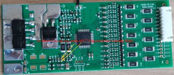
Charging trouble with Smart BMS.

chayr

10 mW
Joined
Jun 11, 2012
Messages
24
Hi all,

For my story, I have same trouble with my two BMS.
I buy 2 of this Smart BMS from "bmsbattery" since 1 year, but when I plug the charger on my 48v 15A lipo battery,
the bms disconnect and voltage shut down at 22-27volt.
The charge don't start more than one or two second then the bms short-cut.

But I can run my bike with the bms connected and it work.

I have an ecitypower charger 48v 4A 240w from "bmsbattery" too.

You have to know after 1 warranty change for a similar trouble, "BmsBattery" after sales service stop answer me and don't whant to try to fix that...

Maybe anyone can help me ???


many people answer me on other post said:
Post by x-speed » Sat Nov 29, 2014 6:35 am

chayr wrote:not full disharged.


and not fully charged (max cell) near BMS OverVoltage Threshold as well, I assume?

chayr wrote:I Try to decrease the charger voltage already with the screw in the charger but it doesn't work and now I have one wonky charger :)
Because I set the 3 screw in the charger to try to shut down voltage.


Is the symptom that the charge will start & stop every 8s for 2s (watch charger LED) ?
Then try to reduce the charge current (Poti VR1 typically on bmsb chargers).
A problem with Charge Overcurrent protection is indeed likely, when OFF after 2s and "4A".

I can confirm that default Charge Overcurrent Setting "5A ordered" (default) may effectively be very near 4A in some cases.
The Charge OC threshold value in the OZ890 chip can be only changed in steps of about 1.25A (=5mV / Rshunt_CpinChargeDirection~4mOhm).
Depending on Current Offset Correction and Rs calibration spread it can thus come near 4A. On one of the last BMSes after detailed calibrations I got effectively with delivered settings and Rs / I calibration measured:

RsChargeCpin = 4.12mOhm
RsDischargePpin = 2.97mOhm
Charge OC Threshold: 4.84 A
OC Delay : 1984 ms
ChargeOC Release Delay : 8 s

(OV/UV Delay Time is yet also 1 Scan Cycles = 1 .. 2 Seconds by delivery default usually)

Re: connections for? EcityP Smart S5-13 BMS

Post by chayr » Sat Nov 29, 2014 5:15 am
Thank you for your helpfull,
The battery is hobbicity lipo bat balanced & not full disharged.

I will recheck it.

I Try to decrease the charger voltage already with the screw in the charger but it doesn't work and now I have one wonky charger :)
Because I set the 3 screw in the charger to try to shut down voltage.

Fortunately I baught twice charger & bms.

Do I have to create my own tread for my trouble ?

Re: connections for? EcityP Smart S5-13 BMS

Post by friendly1uk » Sat Nov 29, 2014 1:00 am
There is a slight possibility the current on the charger is too high. The board is 5 amp, but iirc over reads about 20%. The default settings could be to shut down for this over current event.


What is the packs charge level? is it full? lol

Edit.. Charger voltage could also be to high. Above your chosen value. That would surely trigger a 'full stop' event

Re: connections for? EcityP Smart S5-13 BMS

Post by dnmun » Sat Nov 29, 2014 12:37 am
it sounds like the battery is out of balance and it has one cell hitting the HVC and turning off the BMS charging port. you have to measure cell voltages while it is charging and post them up on a thread about your problem. you should find the high cell right away if you look for it. if you post up the voltages in your own thread we can show you how to make the battery balance if you can do stuff yourself.
 
Another thread on the same subject?
It seems when I spoke to you before you had already had the same story from bmsb.
Have to stuck your meter on the charger yet?
 
friendly1uk said:
What is the packs charge level? is it full? lol

Edit.. Charger voltage could also be to high. Above your chosen value. That would surely trigger a 'full stop' event
Battery voltage is 48,8 Volts
Charger voltage is 54,6 when it's unplug to the battery.

x-speed said:
(OV/UV Delay Time is yet also 1 Scan Cycles = 1 .. 2 Seconds by delivery default usually)
When I start charging BMS the charger light turn green & fan start rotating but only for 1 or 2 sec.
Then all stop, the light turn red & bms voltage shutdown to 22-27 volts.

x-speed said:
and not fully charged (max cell) near BMS OverVoltage Threshold as well, I assume?
The battery voltage is 48,8 Volts & well balanced all 13 cells are at 3,75mV (+/-0,01mV) If I well understand your query.

x-speed said:
Is the symptom that the charge will start & stop every 8s for 2s (watch charger LED) ?
Then try to reduce the charge current (Poti VR1 typically on bmsb chargers).
A problem with Charge Overcurrent protection is indeed likely, when OFF after 2s and "4A".
I try on my first charger to increase the voltage to 53v but it'sn't working.
Maybe I have a resistor that I can plug in series on charger wire.
I risk nothing to try it.


I already succeed load this battery with bms connected.
I plug the charge lead in direct to the battery & stop the charge at 53,5V. Against all odds, all cell was well balanced +/- 0,01mv. (54,6 is max voltage)
I think it's not safe to do that (but I wanted to try the bike who wait more than 1 years :( ). So it's the reason that I stop the load before full charge.
I run the bike without any trouble...
 
I'm struggling with language, so I'm sorry if I misunderstand.

You can reach 3.75v per cell all nice and balanced, but any longer on the charger and it shuts down?

Log in to bmsb and look at your original order.


I'm angling towards the wrong bms settings. Not 3.7v lipo. Your balancing at a low voltage and tripping out at an equally low voltage. That bms is set for a different chemistry. I just don't know anything about other cells to carry on though. I reckon it's 3.3V the other stuff with hvc around 3.8v but would have to look it up. Which I will, If indeed your charger works which battery voltage below 48.8v
 
He has done it dnmun.

He put the charger straight across the cells and let them reach 53.5v as a bulk charge. He then checked each cell, and found them all within 0.01mV

It seems to be balancing fine, it just won't charge past 3.75v per cell. Does that sound right for some other chemistry?
 
friendly1uk said:
I'm struggling with language, so I'm sorry if I misunderstand.
You can reach 3.75v per cell all nice and balanced, but any longer on the charger and it shuts down?
Log in to bmsb and look at your original order.
I understand better what you mean,
I just logged in "bmsbat" and they compltely change their website. I just find that about my last order.
Smart BMS 5~13 Cells in Series - Discharge Current : 20-40A 2 $24.99 $49.98
Alloy Shell 240W LiFePo4/Li-Ion/Lead Acid Battery EBike Charger - AC Voltage : 200V~264V.

friendly1uk said:
I'm angling towards the wrong bms settings. Not 3.7v lipo. Your balancing at a low voltage and tripping out at an equally low voltage. That bms is set for a different chemistry. I just don't know anything about other cells to carry on though. I reckon it's 3.3V the other stuff with hvc around 3.8v but would have to look it up. Which I will, If indeed your charger works which battery voltage below 48.8v
good idea I will try it tomorrow.
For LifePo4 battery cell voltage specifications are :
Min. discharge voltage = 2.5V
Working voltage = 3.0 ~ 3.3 V
Max. charge voltage = 3.6V

So I will discharge my battery to 3volts each cell aprox. 39 volts.
& give a feed back.


There is a long time ago, when "Bmsbat" still answer me, Jack Xie from "bmsbat" told me : "try to reset the BMS" (short cut c7 resistor) but now I have one bms out of course. Voltage shut down directly when I connect it to the battery like when charger is connected.
here is the picture who he gave to me. (don't try this at home it doesn't work for me) :)
smartBMS-reset(1c).jpg
friendly1uk said:
can you expose the BMS and we can show you where to measure the cell voltages on the BMS.
Does the picture in attachment is enough (not mine it's 8S smart bms) but we can see all component of the bms in good quality.
Otherwise I do a picture tomorrow.
 
It is below 4.2 dnmum. All cells are balanced within 0.01v and the total of 13s is 48.8 so they are 3.75v each.

3.75v is some way above 3.6v so my thoughts on this are probably wrong.

I wouldn't pull the cells down to 3v each. I think just getting them below 3.6v would prove it.
I pull mine down to 3v often, but I know I can get them on the charger soon after. At such voltages the balance can drift a bit more, and with no real method of control I would avoid that. Below 3.6v should be enough.


This board is of course the subject of the oz890 thread. There people are able to program these things. Maybe someone will take a look for you.

These boards often need a reset to get them going. I didn't know it could be done at C7. I turn the board over and use the provided pads. You need to connect ground and reset pads together for a moment. Both live side by side. The reset pad is oddly labeled. RTSD or something.
 
I indeed saw once a shipping default smartbms setting of BMSB for LiFe being 3.75v OV Threshold and 3.60v OV Release - in case a wrong programming was done. (I don't use LiFe myself)
However chayr didn't report like "it charged for while, and then OFF too early at rather low voltage" - or was the symptom so?
Was order for LiPo with which values?

The (default) symptom for Charge OC hit (OverCurrent 4..5A) is definitely OFF after 2s, but after 8s again ON and OFF ... periodically. Checked it.
If its not so, the OV hit is likely - in repeated case only when max cell voltage drops below OV Release between charger unplug / replug.

I am not aware of other causes as OC or UV/OV which have that 2s delay symptom.

OV/UV hit may be a indirect symptom of broken balancer cables, or of defect OZ channels or SMD bits. Missing voltages are floating vaguely somehow between. Bn voltages can be checked more directly on the board at the CFn's - being carefull to not cause shorts by slipping probes.

OC/SC could also be a symptom of board errors. more unlikely & more difficult.

The fact of at least 2s charge (repeatedly?), and fact that P- Discharge FET is on (you are really discharging via P- ?), says that the board lives and scans and had no protection hit before charger plugin. advice for "reset" seems strange.
Yet a check of "+V12" (bottom; or top C1 terminal near OZ) for some 10V against B- (GND) is generally a check for valid full boot.
Appearance of +3.3v (C2) but non-appearance of +2.5V (C3) says its correctly booted in "Hardware/Standalone Mode". ( +2.5V ON would indicate "Software Mode" where all protection hits would need explicit reset from outside. )

From your report (charge bypassing the BMS) your charger works ok. Current measurable?

C7 shorting for reset is ok - looked at it: shorts RSTD to GND.
Reset can also be done by this order: Disconnecting balancer plug; disconnecting P+ ; (B- stays connected ); wait >= 2minutes; connect P+ again; (check +3.3V); connect balancer plug.
Having the balancer plug connected while P+ is not on power can reportedly damage the board ! - completely the OZ-CPU or damage channels.

I'd say so far:
#1 definitely exclude the periodic 8s/2s (OC) pattern mentioned. most cheap. (still smells likely)
(#2 Try the reset if it feels simple. cheap.)
#3 swift check of correct sense wire connections / voltages.
#4 Then, playing with lower voltages regarding erroneous LiFe settings or so. Yes, down to 3.0v is very dangerous for a LiPo. max cell somewhat below 3.6v (LiFe UV Release) carefully watching the min cell ... upon charger connect voltage should still have some space up to 3.75v to get some noticeable charge time.
#5 measure CFn voltages (which are very near the OZ) if correctly mirroring the cell voltages without floats/breaks or so
#6 maybe try the 2nd board; make sure for right connection order.

PS: all shorting / voltage probing on the board can be dangerous when slipping ...
 
x-speed said:
The (default) symptom for Charge OC hit (OverCurrent 4..5A) is definitely OFF after 2s, but after 8s again ON and OFF ... periodically. Checked it.
Thanks for sharing that. It clears up another matter for me. I now have no unresolved issues :)

OV is looking very likely now you have confirmed the default. It will be interesting to see what testing reveals. My unresolved issue was the 2/8 on/off cyclic action, on a new board at 3.75v which I think I saw in the paperwork. Sent Crossbreak, tested OK. 20 months it's sat on my mind. Nice to know that the symptom points to my 4A charger.


p.s 3v isn't very dangerous. My lvc is 3v. Manufactures generally say 2.8v
 
friendly1uk said:
p.s 3v isn't very dangerous. My lvc is 3v. Manufactures generally say 2.8v
When a tested bms switches off fast, its ok. But when doing manually or with still questionable bms UV function , voltage may rush down too fast at min cell on Lipo (and some ICR) with steep curves at 3.0v - unlike IMR, NMC and NCA cells.
 
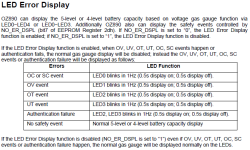
There is another option how one can tell definitely about the protection event cause without I²C just via the 5 LED pads LED0 .. LED4 (open drain - pulling low) on the back of the board:
OZ890-LED-Error-Display.PNG
(NO_ER_DSPL = 0 = "function enabled" is the default from bmsb)
Actually on 2 smartbms I have permanently connected there a compact 7-segment LED display (with common anode[+]) for displaying the gauge levels or error-status, wired like:
* smartbmsLEDpad_i --- 7segLEDkathode_i
* 7segLEDcommon_anode ---1kResistor --- Pushbutton --- B1+ (1st cell voltage).
The pushbutton is there in order to consume small power only while pressing. Of course individual LEDs could also be used.

But one can also measure just temporarily with a Voltmeter the voltage between LEDpad_i and B1+ and look for blinking events or gauge levels.

When no error event is there or when UV, the (non-blinking) configured gauge levels (regarding min voltage cell) are displayed. Regarding my logs before I reprogrammed, bmsb seems to always have default pre-set these levels like:
Gas Gauge V1 : 2.699 V
Gas Gauge V2 : 3.198 V
Gas Gauge V3 : 3.223 V
Gas Gauge V4 : 3.248 V
Gas Gauge V5 : 3.323 V
Thus LiFe kind levels, regardsless if LiIon is ordered.

This way one can also tell if the board is operating and scanning ok, because when there is permanent shutdown error (upon extreme voltages or so), or when ADC scan is off by invalid I²C eeprom command interruption or so, then all leds are permanently off.
 
I couldn't do the test today, I will do it in the week & tell you the result asap !!!
 
Good news !
I succeed to charge my battery !

I run my bike until bms go off (UV) battery voltage go to 44,2V. I can't go lowest because 1 cell go wrong...
I could have, should have been disconnected the bms but I'd rather not take the risk to kill a cell.

Here is the cell volatge (+ to -) :
+ 3,40/3,48/3,51/3,44/3,29/2,88/3,40/3,50/3,40/3,48/3,41/3,44/3,44 -

1st test : I decided to try to charge the battery through the bms. But it was the same thing ... 2 sec & bms shut down. 3,90A Mesured with not so fast multimeter, I think the charger go higher.

2nd : I plug a resistor on the charge wire in serial (see picture in attachment) , the charge go at 0,99A. The resisitor go realy warm.
But there a thing I don't understand. Why if I mesure the curent before or after the resitor it was the same ? (0,99A)
Resistor settings : 10R 5% MO RB58
Re-1.jpg
So I guess you hypothesis was true :D
 
chayr said:
1st test : I decided to try to charge the battery through the bms. But it was the same thing ... 2 sec & bms shut down. 3,90A Mesured with not so fast multimeter, I think the charger go higher.

2nd : I plug a resistor on the charge wire in serial (see picture in attachment) , the charge go at 0,99A. The resisitor go realy warm.
But there a thing I don't understand. Why if I mesure the curent before or after the resitor it was the same ? (0,99A)
Thus OC protection likely (unless voltage raises quickly > 3.75v with 4A which could be still LiFe OV) , and you should see the mentioned 2s / 8s ON OFF pattern with the full "over"current also. (As well as the LED0 blinking)

The current is the same everywhere in a closed circuit :) voltage drops on the resistor.

With one of those 3 pot screws in the charger, could be a "VR1" in bmsb chargers, you can reduce the current smoothly below the OC threshold without resistor - best while measuring. Maybe its just a tiny little below below the "3.90A" .
 
I once observed behaviour that suggested there could be a limit to how far out of balance cells could be. It showed itself by switching the charger on/off for about 15mins around half way through my charging time. This followed an lvc event and a further week without charging that led to a bms reset being required before it would do anything at all. I presumed it was all to far out of balance. I know the low cell should pick up voltage quicker than one about half full, but it really did seem to be kicking in and out cyclically while they leveled out. I have not seen it any other time, or needed to reset any other time. Some relationship was there but I just let to carry on rather than take notes.

Does the oz890 have such a setting? One that will respond to very out of balance situations. I have never read such a thing, but experience has hinted at it.
 
friendly1uk said:
I once observed behaviour that suggested there could be a limit to how far out of balance cells could be.
...
Does the oz890 have such a setting? One that will respond to very out of balance situations. I have never read such a thing, but experience has hinted at it.

yes the Cell Unbalance Threshold , which does trigger a Permanent Failure protection (not just a temporary protection event; requires reset), which switches off all FETs and "+12V" (measurable from outside), and leads to lowest power consuming shutdown mode. This threshold however always had this very high bmsb default:

Cell Unbalance Threshold : 3.198 V
(effective after PF delay, some 12s, of unbalance)

With such high threshold , it has only an effect, when the min voltage cell rushes down below UV to 0V very quickly before the other cells, which usually is the case, when a defect cell enters high self-discharge malady. Or when sense wires are bogus ...

Extreme Voltage Permanent Failures are not enabled by bmsb default. They are more sensitive to sense wire problems, yet require a quick setup connection order or reset after setup connection.
I activate them e.g. like:
Extremely High Voltage : 4.300 V
Extremely Low Voltage : 2.450 V
 
Here is the charger where we can see vr1 vr3 in the midle & vr2 at left upside fuse.
So I have just to turn vr1 screw ? Hope that will work.
I ll try & tell you what happen.
 
yep, VR2 in the corner under the wire that goes out is the trimpot you adjust to change the output voltage. the other ones are for setting the limit on current and the endpoint where it goes over to CV.

i think it is already set to 54.6V from your original text. that is the correct voltage for 13S of li ion.
 
x-speed said:
friendly1uk said:
I once observed behaviour that suggested there could be a limit to how far out of balance cells could be.
...
Does the oz890 have such a setting? One that will respond to very out of balance situations. I have never read such a thing, but experience has hinted at it.

yes the Cell Unbalance Threshold , which does trigger a Permanent Failure protection (not just a temporary protection event; requires reset), which switches off all FETs and "+12V" (measurable from outside), and leads to lowest power consuming shutdown mode. This threshold however always had this very high bmsb default:

Cell Unbalance Threshold : 3.198 V
(effective after PF delay, some 12s, of unbalance)

With such high threshold , it has only an effect, when the min voltage cell rushes down below UV to 0V very quickly before the other cells, which usually is the case, when a defect cell enters high self-discharge malady. Or when sense wires are bogus ...

Extreme Voltage Permanent Failures are not enabled by bmsb default. They are more sensitive to sense wire problems, yet require a quick setup connection order or reset after setup connection.
I activate them e.g. like:
Extremely High Voltage : 4.300 V
Extremely Low Voltage : 2.450 V

Thanks bud. You really know your stuff.
These boards are a real bargain, and will keep me ordering from bmsb until I find another supplier. They seem to be both cheapest and best featured. An unusual combination. I have other boards, but they cost more and are just so basic in function I don't really trust them when things can be this much better.
 
I moved the vr1 screw for 5turns until the charge start.
But charging current is very low I mesured only 1A.
When I try to put more current, bms cutoff :-(

So I m going to charge my 15A battery in 15 hours ?
 
charge to voltages > 3.8V is possible?
And 2s on / 8s off periodically when >1A ?
Then only a reprogramming probably can enable more current.
Either a strange programming or huge offset error.
Or something is ill in the shunt sense circuit.

Did you try the reset?
One could also check if the OZ enters sleep mode correctly after 10min zero current, or always consumes near 1mA: millivolts over 10ohm resistor R17.
Behavior of the 2nd BMS?
 
Yes I try to reset one of my two bms.
But now voltage shut down directly after 8s without charger pluged.
I made a quick video of that trouble :
https://www.youtube.com/watch?v=QP9LlXImvqM&feature=youtube_gdata_player
 
I'm now charging in bulk at 4,5 A
I plan to stop before the end & try to finish the charge at 1A.
I ll tell what happen...
 
Back
Top