Charging trouble with Smart BMS.

so you have now started bulk charging a battery that the BMS had already stopped the charge on because it was at HVC?

what is the voltage on the highest cell in the pack? do you have something to carry it to the bathtub or outside?
 
No, I start the bulk charge to 44V until 52,6 with some check the voltage.
so at 52,6v balance V is :
4,05/4,05/4,05/4,05/4,04/4,05/4,05/4,01/4,04/4,06/4,05/4,05/4,04
BMS was always connected but I plug the charger directly to the battery wire with 4,5A.

After that I plug the charger to BMS charging wire, then I start to charge at 1A.
Start at 52,6V to 54,3 . charger stoped alone.
here is the balance settings :
4,18/4,18/4,18/4,18/4,18/4,18/4,18/4,14/4,17/4,18/4,18/4,18/4,17

You right that charge without bms is dangerous but I stay close all along it was loading. With many check.
And I finish the charge with the bms.
 
x-speed said:
charge to voltages > 3.8V is possible?
Yes I have make the charger at 4,05v with bms

x-speed said:
And 2s on / 8s off periodically when >1A ?
No when the bms cut after 2s it stay off with little voltage around 20v without any power. And It never restart alone.
I have to disconnect and reconnect,for retry to charge. I waited more than a minute.
 
What does the switch in the video do exactly? voltmeters connected where?

How did you do the reset exactly? (E.g. short C7 briefly with pincette carefully on running BMS.)

chayr said:
reset one of my two bms.
Its still all about the BMS #1 always running on the battery? Or did/do you already really run the 2nd BMS? With same ">1A" havior? somewhat confusing story all this ...

chayr said:
But now voltage shut down directly after 8s without charger pluged.
Is that problem pending? or did you do kind of permanent reset pulling??
Is the behavior now (near 4v) half-ok again as before - no damage of BMS? : Charge protection off just when >1A charge; Discharge on P- possible (e.g. on electric iron)?
Beware of wrong P+ & balancer disconnection / connection order of BMS.

chayr said:
No when the bms cut after 2s it stay off with little voltage around 20v without any power. And It never restart alone.
I have to disconnect and reconnect,for retry to charge. I waited more than a minute.

dis-/reconnecting just the charger? or this curios switch / LED-multimeters etc also? or?
A load on P- or C- can hinder the periodic charge restart upon OC protection and other protections - even a voltmeter or LED-voltmeter load. Or even a certain shutdown/powersafe behavior in the charger could hinder the restart.
You could clarify more by: just charger connected with >1A , with no strange (voltmeter) loads. periodic charger on/off then?

Measurement of the mentioned voltage of "LED0" (and other LEDx) vs "B1+" on back of BMS, looking for blinking events, would tell definitely about the cause of protection event - during the protection event of course.


=> Looks still mostly (but not 100%) like erroneous Charge OC setting ">1A" or sense circuit problem.

Then (without I2C) a remaining crucial check from outside is to check carefully - regarding correct sleep-mode - the mentioned milli-voltage (use 200mV range) over the R17 who has 10Ohm ("100" printed on it) - measure after at least 12 minutes idle time after you disconnected all loads (DMMs) and charger, while no protection events.
Is it below 1.0mV ? - while much bigger when charging or discharging?
It would tell about strong offset errors / possible circuit problems.

Then comparison of 2nd BMS behavior.
 
I'm getting a bit lost now. Having the info across two threads is a bane.

iirc both board were the same. Has a second charger been used?
 
x-speed said:
What does the switch in the video do exactly? voltmeters connected where?
switch is connected on relay (2x24= 48) and it cut the B+ before BMS.
Both voltmeters was connected after bms P- & B+ P+.
x-speed said:
How did you do the reset exactly? (E.g. short C7 briefly with pincette carefully on running BMS.)
BMS powered I short cut briefly "RSDT" & "GND" behind C7.

x-speed said:
Is that problem pending? or did you do kind of permanent reset pulling??
Is the behavior now (near 4v) half-ok again as before - no damage of BMS? : Charge protection off just when >1A charge; Discharge on P- possible (e.g. on electric iron)?
Beware of wrong P+ & balancer disconnection / connection order of BMS.

Now the BMS where I make the reset always cut after a few second (see on video).
On the second BMS I didn't do any reset.

Before that I try to charge & run with each BMS. And both have the same trouble of bad charge.
After a reset of one BMS, it go wrong like video shown.


I have an I2C to USB connector, but I read that it's more complicated to connect BMS on PC.
"Aardvark I2C/SPI Host Adapter is needed"
Or you have an issue to connect on pc ? :D

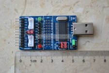
I find an chinese "ALL IN 1 USB to SPI/I2C/IIC/UART/TTL/ISP serial Adapter" but I not trust on quality...
 
chayr said:
switch is connected on relay (2x24= 48) and it cut the B+ before BMS.
Both voltmeters was connected after bms P- & B+ P+.
hmm, how exactly does the relay(s) cut and why!?
If you have cut bms P+ off from Battery+ while you have the balancer plug (B0..B13+) connected or any other power, this is the mentioned condition known from several cases to damage/kill smartBMS - e.g. in some threads of this forum. Did you do this practice from beginning? Or what was your setup BMS connection order? and BMS disconnection order?
(Being aware of, I didn't dare to make this "20$-test" intentionally ever, to fully confirm those damage stories.)
I mentioned this condition extra in an earlier post here to warn avoiding this under any circumstances.
From datasheet:
OZ890 power first.PNG(VCC --> P+ pad; Ground --> B- pad)

chayr said:
Now the BMS where I make the reset always cut after a few second (see on video).
On the second BMS I didn't do any reset.
So you say, the one reset'ed BMS permanently irreversibly changed/worsened its behavior - sort of more defect than the other? No discharge possible? Reset was done while P+ was cut off?
This sadly would make more likely that you have/had balancer plug on, while P+ disconnected ... you mention such important things very late ...

I'd recommend to become very aware of right connection/disconnection order before possible risking on the 2nd BMS - which with some probability may be already half defect.

Question is now, if you want live with that half-functioning BMS#2 as it is now? (>1A charge problem only; check of correct critical functions OV/UV recommended; avoid P+ cutting)
Or (b) if you are interested to analyze the condition of at least the better bms more exactly without I2C first? (Rather precise answers about the questions left regarding LEDx , R17/sleepmode and exact voltages "+V3.3", "+V12"; is there 2s charge restart by dis-/reconnecting just the charger? ...)
Or if you want try to deal with bmsbattery - though you perhaps damaged things yourself ...
Or ...

I2C check/programming (after (b) perhaps) with standard interface is possible but complicated byte peeking&poking. More or less HW damage of both BMS'es yet may already be the situation; prospects of cure by I2C are not 100%.
A $100 I2C interface with OZ/SmartBMS PC software exist from bmsbattery.
I use since long time a own Bluetooth I2C hardware with own Android & PC software for OZ890/SmartBMS for advanced logging, programming etc - example log curve here.
 
A switch between the cells and bms on the big red wire?

If it were not 13s that would kill it outright. However R1 still connects the top of cell 13 to P+ regardless of the switch. R1 should always link P+ to the top cell, but bmsb don't do so when they mod the boards so only 13s boards are sent out correct.

This leaves an odd situation. The board may not of produced smoke, but who knows what else might of happened.
 
friendly1uk said:
If it were not 13s that would kill it outright. However R1 still connects the top of cell 13 to P+ regardless of the switch. R1 should always link P+ to the top cell, but bmsb don't do so when they mod the boards so only 13s boards are sent out correct.

For N<13 bmsb shorts the upper CFx (not really the best solution) which yet creates a situation almost "as good" as for 13s.
However R1, which is high 10k also, does not conduct back from BAT13 to P+/VCC because of diode D2 - just the other way around! That may be so because bms power supply current on the max sense wire in regular case would somewhat influence cell voltage readings. Thus it probably doesn't help regarding damage protection.

Thats why I add a extra reverse diode which shall provide P+/VCC via Bmax+ in case of P+ cable break or so and make it more fool proof/robust regarding that problem. Though the voltage will be a diode less than normal, as of now I hope this will do the precaution job in most cases. Yet I didn't make the "20$-test" intentionally so far :)
 
ooo diode. I missed that. It was not important to me before.
Where did you add another? Straight on top of it, like it had been removed?


I had a bad board, so pulled main power. I had installed the balance leds, and most seemed to light up while the fets smoked. No exact story, as a burning board had me disconnecting at quite a rate.
 
friendly1uk said:
ooo diode. I missed that. It was not important to me before.
Where did you add another? Straight on top of it, like it had been removed?
no, reverse direction over D2 and R1, so that there is no huge voltage drop over R1 in the case of the P+ cable break.
So in regular normal case (with P+ wired) there doesn't flow current over the added reverse diode, because the direct P+ cable current doesn't run over diode voltage drop - thus no influence on precise cell voltage sensing in regular case.

friendly1uk said:
I had a bad board, so pulled main power. I had installed the balance leds, and most seemed to light up while the fets smoked. No exact story, as a burning board had me disconnecting at quite a rate.
Is this such case where the balancer plug was on, while P+ was not connected, and then the board was killed? Any details about exact story would interest me.
 
I see what you did now.

On the board in question, I shorted the charge wires, blowing an output fet and the resistor that protects the chip. It was probably brain dead at this point. I cleaned up the mess, and wired across the resistor. The board did nothing. So I pulled main power and then the battery side of the board smoked.

I have since done it again. Another board. Shorted charger. An output fet in bits. People reading will think I mean charge fet, but charge current goes through the outputs where it is measured. I have done nothing with that board, so I dunno if the resistor feeding the chip is blown. I just know the short circuit current is inadequately monitored from factory. Though it is adjustable in the software.

This latest board is a 13s lipo 3v-4.25v to stop a 4.2v charger hitting the hvc every charge. It could perhaps be saved. Though I'm not going to give it away to someone unless they know how to use it.
This 4.25v setting is an experiment. I have no idea what balancing threshold they will of set. I'm just hoping it is 4.2v or under. I'm quite sure it will be..
 
friendly1uk said:
On the board in question, I shorted the charge wires, blowing an output fet and the resistor that protects the chip. It was probably brain dead at this point. I cleaned up the mess, and wired across the resistor. The board did nothing. So I pulled main power and then the battery side of the board smoked.
So this case may not be too specific for the problem of P+ off while balancer wires ON as it, but mixed/subsequent with a previous problem of blown R17 and attempt to recover.

Regarding the shortcut on charge connector (C-) I had one such case, where I had a coaxial power connector on that charge port. I wanted to measure with a DMM, did it sloppily directly without a matching plug on the rush, thereby shorted the connector with a probe. A very short knack happened, much shorter and milder than a shortcut I experienced in similiar szenario on a car-fuse fused lead acid battery once (where half of a connector pin melted away). There was only a small melt dot on one connector pin after that, not hindering its further use. As I continued measuring the voltage immediately after that I recognized for some seconds a somewhat deeper voltage (indicating FET off, just small bypass resistors R20/R24 active), which then recovered to full voltage, and all worked ok then as if nothing happened.
I looked up the (bmsb default) settings which were active:
SC Threshold : 100 A
SC Delay : 496 µs
SCRC: 0 (=reset by SCRL pin, not by time delay)
The time delayed non-immediate reset observed may have to do with a indirect OC triggered by the SC OFF, as the discharge FET switches off which acts as a sense resistor too in the SmartBMS and simulates a OC.
Thus in this case the SC protection seemed to work as it is perhaps intended. SC works in all modes, during sleep also.

I wonder yet what happens when the shortcut happens behind a long cable with significant inductance. In the datasheet circuit there is a D1 which should protect SCRL and DischargeFET effectively from high inductive energy&voltage (>Battery+) easily. Yet I can't find the corresponding diode on the smartbms board. This may be an issue as I consider now.
I also know that on older smartbms boards there was a layout error for long time: the big C4, which shall supports VCC (P+ behind D4 R17), and which perhaps is not unimportant in extreme conditions, was not connected on the ground side (thus without effect) - one can even see this on the pic from bmsb which chayr posted in this thread. This error is fixed on newer boards.
Maybe for low-Ri LiPo's a shorter SC Delay is reasonable.
 
I guess I do wrong assembly sequence.
But how can I disconnect battery power when I park my bike ?
I thought it was good to cut B+ with relay but I'm wrong :-(
Do I have to get always BMS connected on battery and cut power after the bms ?

So in summary what you advise me to do for my charging trouble?

so sad :( lol
 
Ok I'm starting a collection of bms. :)

Thanks anyway to all people help me in this thread.
It was really interesting to talk with you.
 
I used a co-axial plug to. Only I was nipping the nut up as it had come loose. Slipped and bang. Crossbreak also questioned the 0.5ms

Bestech boards are dumb comparator based things. Old fashioned stuff that does not detect bad cells well. Even if a cell drops to zero, it will still try and charge. About as much use here as raising charger voltage.


bmsb will ask about $50 to post out a new board. Perhaps you could add a few other bits to spread the postage cost. Though $50 for a $20 board is still cheaper than most alternative dumb boards on offer. Bestech included.

If your still on the first charger I would pick up another. We have not really looked at it, and they do fail so a spare is always handy.
 
chayr said:
I guess I do wrong assembly sequence.
But how can I disconnect battery power when I park my bike ?
I thought it was good to cut B+ with relay but I'm wrong :-(
Do I have to get always BMS connected on battery and cut power after the bms ?

So in summary what you advise me to do for my charging trouble?

so sad :( lol

Status remains vague overall after your report. half-damage, no full protection ... ?
If really continuing using with low charge current, you should at least test if the other essential protections really work. This should be done with any bms.

You didn't fully confirm if you disconnected P+ (bms) from Battery+ (assume you mean that by "B+") by the relay. or you just disconnected other things. And if you did the RSTD reset trial while P+ was disconnected. And actual assambly sequence. Would be interesting for us to learn more if and how damage goes on or goes worse exactly.

Anyhow P+ vs B- on bms needs to be powered before the balancer inputs have voltage. Thats the special the requirement.
Other analog bms do not have P+ , they draw (lot of) power through the balancer wires. Maybe that simplification makes it easier. Analog bms have many drawbacks and limitations on the other hand.

Bmsb doesn't write this special requirement clearly on the website, in the doc-pics or anywhere else as far as I remember. So you may principally request a refund with your case description. Particularly if you are in PayPal time limit. Maybe at least you get them adding that info about right connection order in future.

A BMS is meant to stay on the battery. to fully do its protection job. It would draw power through balancer wires otherwise also.
The smartbms unlike analog bms does consume only 60µA during sleep. Thus only some 40mAh per month.
You cannot really replace a 48V relay by 2 x 24V relays.
( With OZ890/smartbms there would be an advanced option using EFETC pin to turn the BMS FETs off with "powerless" small switch - not requiring an extra power relay. )
 
x-speed said:
I use since long time a own Bluetooth I2C hardware with own Android & PC software for OZ890/SmartBMS for advanced logging, programming etc - example log curve here.

Could you tell me what is your tool & software for a DIY usb i2c ?

I have an usb i2c standar key but I find this one. It is an all in one Uart i2c ... to usb.
Do you think it can replace the bmsbattery tool ?
USB-ALL-IN.jpg
 
nope. the cowboy tool only works with the original o2micro adapter you can buy for $99

nice to hear the C4 main cap issue was finally solved. i ordered my last batch in june and still got boards that had the issue.

The 496us SC delay are quite long. You need it that way: if you dont use precharge resistors when connecting to the ebike controller (that snaps, cause the caps of your controller get charged in an instant which damages both your connectors and caps over time), since the BMS go into SC mode with lower values.

I swapped my plugs to XT90s ones that have built in precharge and could lower the value to ~50us or so if i remember right. If i now do a shortcut, i dont even hear much of a snap.
 
x-speed said:
chayr said:
( With OZ890/smartbms there would be an advanced option using EFETC pin to turn the BMS FETs off with "powerless" small switch - not requiring an extra power relay. )
Which pin is this? Where to connect?
 
Power switch?
yes please! tell me more. I want to use these in them 09 square bottle batteries with the built in power switch. I thought I would have to blag it.
 
from the datasheet Page 5
EFETC; Pin 32 ; I/O External MOSFET control signal; it can be configured to input or output through setting EEPROM register

it's tied to ground with a 470 ohm resistor R38 on the ecitypower boards (close to the i2c plug). The application note 11, page 2 (5-13s li-ion application in HW mode), states no value, in the schematic it is tied to ground via resistor R34
 
crossbreak said:
but as someone stated arleady somewhere around here, you can as well add a switch to the external NTC temp probe. If you open this switch the BMS will go into overtemp protect and will shut down the FETs as well.
the ouput does not switch off. Only the charger as you can see below. Load is 10Amps.
BMS3.jpg
 
Back
Top