Charging trouble with Smart BMS.

x-speed said:
The (default) symptom for Charge OC hit (OverCurrent 4..5A)is definitely OFF after 2s, but after 8s again ON and OFF ... periodically. Checked it.
If its not so, the OV hit is likely - in repeated case only when max cell voltage drops below OV Release between charger unplug / replug.

Hi all, sorry for long time without news but I'm very busy this few days... :)

So I unplug the relay, and I pluged BMS directly after the battery with the good assembly sequence.
So now I see that "x-speed" said in a last post : "charge is definitely OFF after 2s, but after 8s again ON and OFF ... periodically."
I don't know if it's important or not...

I still can't charge more than 1A.
 
I guess I find something interesting.
I check CFx like "x-speed told" since the beginning... :roll:
When I check voltage through CFx, I can't find any voltage after CF0>>>CF1.
After other CFx I find +/- 3.7v

With ohmeter nothing for CF0. Other CFx give approximately same resist 0,23(n?) (I notice it's grow up after disconect battery)
 
bgt said:
crossbreak said:
but as someone stated arleady somewhere around here, you can as well add a switch to the external NTC temp probe. If you open this switch the BMS will go into overtemp protect and will shut down the FETs as well.
the ouput does not switch off. Only the charger as you can see below. Load is 10Amps.
BMS3.jpg
If you connect a charger, you should see positive current. On your Pic you can clearly see that you have an OC event. So the fets are both off. If the FETs are off, the current readings are always false since this fail design BMS misuses the discharge FETs as shunt. Sure there is a lot a lot off drop across these if they are off...so you see some large ghost current
 
Crossbreak, the Fets are both on. A charger will give positive results in mA. But the -30C does not switch ther Fets off :roll:
 
That's strange. No idea how it behaves with multiple events. Still with two at the same time it should really turn the FETs off. Sounds like your chip is totally bricked. Better get a new board..does it at least turn off if you overcharge or shortcircuit? Maybe your FETs are faulty?
 
The UT timer is also at 10. Only possible reason that comes to my mind is that your FETs are faulty. Did a lit of testing with these boards but never have experienced a behavior like this. With multiple events mine did always shut off the FETs. I eveb have a board that is completely dead on i2c but behaves absolutely normal in all otber manners
 
crossbreak said:
The UT timer is also at 10. Only possible reason that comes to my mind is that your FETs are faulty. Did a lit of testing with these boards but never have experienced a behavior like this. With multiple events mine did always shut off the FETs. I eveb have a board that is completely dead on i2c but behaves absolutely normal in all otber manners
The Fets are ok. They switch off if you do the calibration setup with the 2 currents= 0 ma and 10A(in my case). It switches off after the second value calibration. I do the calibration with -10.000ma. If I do it with a +10.000ma then it is totally corrupted. I have 2 SmartBMS boards here and they both are working perfectly and they also beheave and work exactly the same.
 
chayr said:
x-speed said:
The (default) symptom for Charge OC hit (OverCurrent 4..5A)is definitely OFF after 2s, but after 8s again ON and OFF ... periodically. Checked it.
If its not so, the OV hit is likely - in repeated case only when max cell voltage drops below OV Release between charger unplug / replug.

Hi all, sorry for long time without news but I'm very busy this few days... :)

So I unplug the relay, and I pluged BMS directly after the battery with the good assembly sequence.
So now I see that "x-speed" said in a last post : "charge is definitely OFF after 2s, but after 8s again ON and OFF ... periodically."
I don't know if it's important or not...

I still can't charge more than 1A.

So do you observe that 2s/8s ON/OFF pattern ("OC hit") whenever charger is set for >1A - or other symptom ?
And does OV / UV protection work really reliable?

chayr said:
When I check voltage through CFx, I can't find any voltage after CF0>>>CF1.
After other CFx I find +/- 3.7v
0 volt over CF0 and cell voltage over higher CFx is normal. Those Ohm measurements over CFx don't make much sense.

The mentioned gauge & error LED signal analysis tells more about the situation - in case you are still hoping/trying on the BMS #2.
A OV protection test is the most crucial test finally (best perhaps repeatedly) before relying on a bms setup. LiPo's of such size and in everyday EV application are rather dangerous - even with ok BMS. Thats why I repeat these warnings :) (I'm using only brand 18650 today; hardly a good reason today for LiPo's in EV's )
 
crossbreak said:
I swapped my plugs to XT90s ones that have built in precharge and could lower the value to ~50us or so if i remember right. If i now do a shortcut, i dont even hear much of a snap.

Thus you made shortcut(s) intentionally recently and things survived as in my accidential case. Was the C4 already connected ok at that time? And how low-R is the battery approximately?
 
Continuing on that shortcut / FET damage problem:
friendly1uk said:
I shorted the charge wires, blowing an output fet and the resistor that protects the chip. It was probably brain dead at this point. I cleaned up the mess, and wired across the resistor. The board did nothing. So I pulled main power and then the battery side of the board smoked.

I have since done it again. Another board. Shorted charger. An output fet in bits. People reading will think I mean charge fet, but charge current goes through the outputs where it is measured. ...
friendly1uk said:
I used a co-axial plug to. Only I was nipping the nut up as it had come loose. Slipped and bang. Crossbreak also questioned the 0.5ms
A typical ebike battery+cable resistance & controller capacitor yields a onset boot current peak of some 0.150Ohm * 1000µF = 150µs duration ; peak current of some 300A which is >100A SC threshold during that RC time roughly. With boot contact resistor (e.g. 33Ohm which I have on one setup) the SC condition may never arise at all during plug in.
I tried the shorter 250µs last weeks on all batteries, which still resulted in correct boot in all circumstances. Yet the 500µs bmsb default value is not so unreasonable as a general preset - some reserve time. A low resistance LiPo boots the cap faster and peak current is higher.

However I think SC delay tuning and thus regular Rds_on ohmic power dissipation within 0.5ms in the 2 or 3 output FETs is not the cause of that FET destruction problem. 3mOhm * 600A² * 0.5ms on 2 or 3 FETs is not enough. And the single charge FET should be dead first in that story.
Thus I still think the 2 mentioned potential causes are more likely (which happen during transition or irregular control):

* The former C4 layout error. See the red and green circle in the pic below. The C4 is crucial for OZ VCC support during hard shortcut, so problems of partial reset, low discharge FET gate voltage etc are likely when C4 was not connected - more likely in combination with rather high LiPo peak currents.

* Inductive problems with missing flyback diode at the time of SC protection OFF - also likely in combination with rather high LiPo peak currents. I found the unequipped "D5" spot on board: the blue "Flyback Diode" in the pic below (= "D1" in OZ circuit diagram). High voltage can attack the SCRL pin. The cable inductance is "charged" very fast within L/R < 5µs typically.
Both ohmic dissipation and inductive "avalanche breakdown energy" problems go up like ~Amps² , and problem probabiltiy can add up with Amps.

OZ890-smartbms-C4-problem s.JPG(the pink diode is that "reverse" emergency bms power diode as discussed earlier)

Questions which can help to discern:
* Did the 2 destroyed boards have the C4 unconnected at that time?
* Was only one of the 2 or 3 output FETs destroyed (heavily/visibly), or were all output FETS destroyed equally ?
* Do you have a guess about the resistance (R_AC or R_DC@10s ... ) of the battery in use during that events?
 
D5 is not a 'flyback diode'. it is set there to allow the TVS to blow up if the input voltage P+ is reversed in polarity. it is there to protect the microprocessor and the other active devices from reversed voltages.
 
The EFETC pin can be configured for different FET off actions and for OZ shut down (Active "1" when pulled high / 3.3v) . The default config is for Charge OFF function only. The function is immediate - can even be used for pwm.
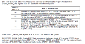
OZ890 EFETC pin functions.PNG
To switch off the bike on a permanently mounted battery, usually one wants to switch the discharge FET off.
The problem with discharge FET off function (also during delayed OT trick and other protection causes) on the bmsb SmartBMS is that the discharge FETs are used as current measurement shunts, and there are bypass resistors R20/R24 which are switched by small FETs which are controlled by V12 (ON unless OZ is in shut down state) (The FET shunt has the advantage of lower total resistance)


Thus as soon as the discharge FET is shut off by whatever reason, and the load (ebike) is still connected, the OZ will usually not return from indirectly caused SC/OC protection event, even if the switch is released. So normally a load disconnect and reconnect is required - which would make the switch solution questionable - you could plug off right directly.

Here for example I logged once a UV protection off event during ride - after UV hit (bad cell 4) , the current reading jumps to high virtual charge currents, and a SC/SC+OC protection state is pending after the first UV off (and quick UV release) - continuing until disconnecting/reconnecting manually :
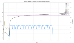
smartbms-UVoff-OCSCindirect s.PNG
(CheckStatus curve represents the "FET Disable Register" mainly here, thus the swinging is mainly between SC and SC+OC until disconnect/reconnect)

Also when a error is pending like OT / SC/OC then the bms is not going to sleep and draws rather high current (some 1..2 mA) permanently. And a current of some 10mA is continuously flowing via the bypass resistors into the connected load.

So more advanced means are necessary to realize a isolating and recovering load switching on the SmartBMS:
Implementing a real shunt & strip the bypass; Or a trick like this could perhaps do:
* configure EFETC for shutdown function (EFETC_SHDN_ENB = 1)
* wire a small pushbutton which puts a HIGH/3.3v puls on the EFETC pin (R38) - for switch OFF
* wire a 2nd pushbutton which puts a low puls on RSTD (C7 or on board back) - for switch ON again

So one would have 2 small buttons for tapping. During shutdown currents are lowest, and the bypass current is shut off.
I have not done this switch, as I had no use for that so far. But from one experiment I know that via a reset puls the currents came up without requiring disconnect, which is crucial. However this was a small load. Maybe sb will try if this works out in practice ...
 
x-speed, great find.Thanx.
I can better use an external relay, easier to implement and working alright.
 
dnmun said:
D5 is not a 'flyback diode'. it is set there to allow the TVS to blow up if the input voltage P+ is reversed in polarity. it is there to protect the microprocessor and the other active devices from reversed voltages.

The D5 cuts reverse voltages whenever P- goes beyond P+. This happens quite typically when a inductive load between P- (or C-) & P+ is switched off by the Discharge FET. A cable inductivity as it plus high SC currents plus SC protection FET OFF is also right such a critical situation.

Here this Flyback diagram from http://en.wikipedia.org/wiki/Flyback_diode shows the typical scenario:
300px-Flyback_Diode.svg.png

Things can be matched 1:1 on our SC OFF situation: Vs = Battery, R L = shorted load cable (or charge cable via charge FET), D = D5 flyback, t0 switch = Discharge FET going off by SC protection event.
The D5 would protect the Dis FET (and SCRL) from in such situation.

The "TVS1" on the pic (also unequipped, same name in the circuit diagram) between P+ and GND/B- is a Z (60V) with shall protect P+/VCC from overvoltages - e.g. recuperation pulses, mad chargers.
 
x-speed said:
Thus you made shortcut(s) intentionally recently and things survived as in my accidential case. Was the C4 already connected ok at that time? And how low-R is the battery approximately?

Pack Ri is about 50mOhm. C4 is the first thing is solder when i got hands on such a board.

Thanks for the input in the flyback diode D5. something everyone should consider.

Also the "emergency diode" that only works in 13s, unless the unused CFx are shorted. I have a mini ANL fuse in series to the battery and B+. It never blew, but if it would, i hope this diode would keep power for the oz890 so it should not be killed by the CFx voltages, i guess?
 
Back
Top