College Class electric tadpole trike build thread

ggc-honors

1 mW
Joined
Sep 16, 2015
Messages
13
Hello,

My name is "Dr. Ted" from a college in Georgia. Because of FERPA, I'll be using only my first name and ask my students to only use their first names as well.

We are going to build an electric tadpole trike. We are 5 weeks into the build and expect it to take at least until December, and possibly until May. (We will spend either one or two semesters on the course.) This class fulfills the non-major science requirement for my students. They are all college students who are not science majors and have no experience building anything.

Here is what we know so far:
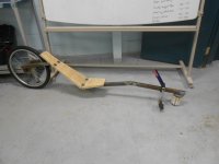
- We are following directions from atomiczombie.com for the "warrior" tadpole trike.
- This is a "from scratch" build, but we will, of course, use some off the shelf parts.
- We are also taking inspiration from Matt Shumaker's 50 mph trike. (http://endless-sphere.com/forums/viewtopic.php?f=28&t=15634)
- Motor: Astroflight 3220 5-turn
- ESC: Castle Creations Phoenix 160A
- Batteries: 12s 15,000 mAh LiPo (Hobbyking)
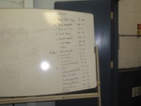
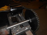
- Gear ratios: [strike]Stage 1: 17:50, Stage 2: 13:80.[/strike]
Stage 1: 9:48 Motor RPM = 6000, shaft RPM = 1125
Stage 2: 16:44 Wheel RPM = 409.
- [strike]Final "nominal" speed: about 27mph.[/strike]
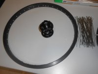
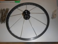
Nominal speed on 26" rear wheel = 31 mph

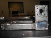
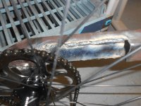
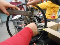
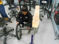
Each student took a turn on the welder and got some experience welding.

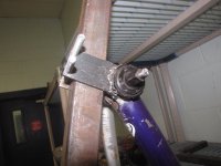
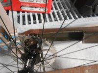
We currently have the main part of the frame welded together with the read wheel mount. We are working of the front wheel mounts next.

We have a lot to do, and we will post pictures as we go. I look forward to any suggestions along the way.
 
Before I knew that I had financing from the school, I was thinking I'd go with a hobbyking motor and esc combination. One of these motors possibly?

https://www.hobbyking.com/hobbyking/store/uh_viewItem.asp?idproduct=21968
https://www.hobbyking.com/hobbyking/store/uh_viewItem.asp?idproduct=37460
http://www.hobbyking.com/hobbyking/store/__25413__Turnigy_RotoMax_150cc_Size_Brushless_Outrunner_Motor.html
http://www.hobbyking.com/hobbyking/store/__14426__Turnigy_CA80_80_Brushless_Outrunner_50_80cc_Eq_.html

The first two spin really fast and would have to use 8s battery and be gear reduced even more than the astroflight.
The third is almost as expensive as the astroflight.
The fourth might be a good option if I was trying to budget parts.

One of these escs, depending on which motor:
http://hobbyking.com/hobbyking/store/__24754__Turnigy_Trackstar_1_5th_Scale_Sensorless_200amp_8s_Opto_Car_ESC.html
http://hobbyking.com/hobbyking/store/__17981__Turnigy_dlux_160A_HV_Brushless_Speed_Controller_OPTO_.html

This is my first time running this class, so I made these choices for the students before the class started. In the future, we may try other options.

-Dr. Ted
 
Oh, wow. I just saw your username and signature. I'm looking forward to any advise you can offer.
 
Its a good thing you didn't buy the Rotomax. It has an issue with inductance (that I don't truly understand yet). These motors are designed to be lightly loaded and to accelerate to top RPMs in very few seconds (when on a light RC model). When using them on an Ebike, they are under much more load, and take many times longer to get up to speed.

Matt Shumaker is the resident expert on Astro motors. He added low-ESR capacitors to the input of the chosen ESC (to reduce voltage ripple and voltage spikes), and even then...he also had to add a slip-clutch to the drives' output so the motor wouldn't bog down, even if the bike did. If you are set on the Astro motor, describe what you will have in the tadpole build, and then do exactly as Matt recommends to do.

Of course there are other motor options, but each has its unique benefit / drawback profile...

Atomic Zombie "Warrior"

FRITZ_SCHANTZ@ARTIES_WARRIOR@USA@04-17-2012@L.JPG
 
I am here to advise you on whatever you need. I can get you the motor and esc if you would like.

There are some very specific things you need to do to make your system work properly. These systems can run very powerfully and reliably, but you need to set it up properly. I can walk you through those specifics. PM me your number and we can talk if you would like.

Matt
 
A couple of comments about the atomiczombie.com plans.

1) The plans are amazingly detailed and step-by-step. Perfect for a first time builder.
2) I e-mailed the side owner and asked about using the plans for a college course. I was prepared to require each student to buy a set of plans as their "textbook." They told me we could use the plans without additional charge. (I had already purchased one set for myself years earlier.) To my mind - these are "good people."
3) The warrior frame may be a little "light weight" for an electric conversion. We will see.

-Dr. Ted
 
Dr ted I have found the warrior design to work well and is plenty strong. One thing I would recommend is to go with a better seat. You can see from the photos in my build thread I went pretty much with the style of seat suggested from AZ. I have found when laying back in this seat the road shock kind of blurs my vision once you get up to speed. Younger riders as your students may fine with this but it is an issue for me. I notice on the photo in the first post the warrior here has no under seat steering? I would go with the under seat steering as it's not that much extra work. Good luck on the build..........Wayne
 
Wayne,

The picture in the thread wasn't from me. We were planning on using the under seat steering. I'm glad to hear that the frame is strong enough.

-Dr. Ted
 
Dr. Ted ~ if the course is a success, and looks to continue or "grow up" the EV food-chain a little bit, you/faculty should check out Switch Vehicles :
http://switchvehicles.com/
http://www.theswitchlab.com/

They provide kits, but also specifically curriculum for EV building courses.
 
Dr. Ted ~ if the course is a success, and looks to continue or "grow up" the EV food-chain a little bit, you/faculty should check out Switch Vehicles :
http://switchvehicles.com/
http://www.theswitchlab.com/

Yes, yes and YES! If we prove ourselves with this course, we might be able to get some external funding. After just a quick glance, that looks awesome! I need to see what it costs.
 
Some pictures. Right now it is just a fairly standard atomiczombie.com warrior frame. I also found a pic of students working in the shop with no faces visible.

20150921_frame.jpg

20150921_shop.jpg

Dr. Ted
 
Monday group got a lot of work done! Mostly worked on parts for the rear

got a great start on the pedal pieces

-Ky
 

Attachments

  • IMG_0872.jpg
    IMG_0872.jpg
    64.2 KB · Views: 538
  • IMG_0857.jpg
    IMG_0857.jpg
    99.3 KB · Views: 538
  • IMG_0854.jpg
    IMG_0854.jpg
    95.1 KB · Views: 538
Attached pictures show:
-The home made drive we will be using. The astroflight motor mounts to a frame which will also hold the 3/4" shaft. The motor has a 9 tooth chain sprocket and the shaft has a 40 tooth sprocket. The large sprocket is held in place with clamps and prevented from rotating with a ANSI key.
- The drive mount without the drive components. We are still waiting on the pillow block bearings and the sprockets to drive the wheel.
- The frame with the seat and petals installed.

-Dr. Ted
 

Attachments

  • drive_1.jpg
    drive_1.jpg
    183.7 KB · Views: 1,278
  • drive_mount_2.jpg
    drive_mount_2.jpg
    220.8 KB · Views: 1,278
  • frame_with_seat.jpg
    frame_with_seat.jpg
    193.6 KB · Views: 1,278
The local bike shops either didn't have someone who could build wheels (lace the spokes) or were backed up for weeks and could meet our time frame. Time to learn something new! My students did a great job building the wheels. They came out straight and will need very little adjustment at the shop.

-Dr. Ted
 

Attachments

  • wheels1.JPG
    wheels1.JPG
    99.8 KB · Views: 1,210
  • wheel2.JPG
    wheel2.JPG
    106.7 KB · Views: 1,210
For the drive system, we are using a #35 chain from the motor to a center shaft, and then a single speed bicycle chain from the center shaft to the rear wheel. To mount the rear drive sprocket to the rear wheel we used the 6-bolt pattern for the disk brake (opposite of the normal drive gears.) The sprocket we found was meant for a crank, so we drilled the six mount holes and enlarged the center hole so that it would fit on the rear wheel.

Unfortunately, when we mounted the rear wheel with the drive gear mounted to the disk brake side, we found that there was interference with the rear "fork." We cut out a portion of the rear fork and reinforced it so that the sprocket and chain have plenty of room. We will see if the strength is degraded too much.
 

Attachments

  • drive_gear2.jpg
    drive_gear2.jpg
    214 KB · Views: 1,206
  • drive_gear3.jpg
    drive_gear3.jpg
    239.9 KB · Views: 1,206
In the first image, my students are using a hand drill to drill a 5/8" hole through 1/2" steel rod. Next year I'm asking for a drill press. :D

The second picture shows the 1/2 inch bar welded to the bottom of a shortened fork tube and mounted to the front wheel.

The last two pictures show the arm which will attach the front wheel to the bike frame. In about a week we should have a trike we can sit on!
 

Attachments

  • wheel_mount_1.jpg
    wheel_mount_1.jpg
    259.3 KB · Views: 1,206
  • wheel_mount_2.jpg
    wheel_mount_2.jpg
    239.2 KB · Views: 1,206
  • wheel_mount_3.jpg
    wheel_mount_3.jpg
    218.4 KB · Views: 1,206
  • wheel_mount_4.jpg
    wheel_mount_4.jpg
    251.6 KB · Views: 1,206
Back
Top