Hi everyone,
I purchased a turn-key electric bike from BTwin/Decathlon which can be seen here:
http://www.decathlon.ie/original-700-36v-electric-bike-en-s152571.html
The 250W motor, controller, connectors etc. are all stamped with "8FUN" logos, but based on research 8FUN and Bafang seem to be the same company so I guess their controllers are the same, the controller looks like any of these, except mine is in a black box:
8Fun:
http://shop.8fun-motor.com/controller/12-cr-s106350sn.html
Bafang:
http://www.szbaf.com/en/components/component/controller/cr-s105250sq.html
http://www.szbaf.com/en/components/component/controller/cr-s105250sn.html
With the difference between the Bafang ones being the 'control type' -one is a square wave and the other says sine wave...I'm not sure what this means / which type I have or how to find out.
My problem is that I want to connect a throttle input to the bike, the websites above say that a throttle can be connected ("Throttle Voltage Input DC 1.0-3.9 V") but I am not sure how to do so. The wiring loom that came with the bike only has 3 connectors at the front (2 for the brakes, 1 for the display, and a little cable for the lights, NO throttle input connector). I purchased a new wiring loom from Green Bike Kit which can be seen here that does have 4 connectors:
http://www.greenbikekit.com/bafang-bbs01-bbs02-central-driven-kit-eb-bus-cable.html
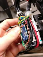
There are 8 wires from the main connector from the front of the bike to the controller with the following colours and detective work to figure out what they are:
White (brake signal), rests @ 5V, 0V when brake is depressed
Black (GND)
Orangey pink (VCC) - 40V when display is turned on
Brown (Power for display) - 40V even when display is turned off
Green (TX) - digital signal from display (+ and - levels of assist selected by rider pushing buttons etc. )
Yellow (RX) - digital signal from display (+ and - levels of assist selected by rider pushing buttons etc.)
Blue - wire for front lights that goes to small blue circuitboard separate from main board
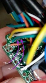
Red - Most interesting, at 3.3V when connector for both brakes are disconnected at front, at 0V when either brake connector is connected
The red wire of interest is the one pictured here beside my thumb: (hopefully attaches at the end of this post...)

So basically my new 4 connector wiring loom arrived today (linked above), which has a dedicated connector for a throttle input, I connected the normal 3 connectors to it as before (front display unit and both brakes) and everything worked with the bike as before (except the now disconnected front light!)
I also was brave and decided to connect a throttle to the 4th connector:
http://www.greenbikekit.com/wuxing-left-half-twist-throttle-for-bafang-bbs01-bbs02.html
Nothing happened when I turned the throttle (motor didn't start) - the bike also has a PAS sensor so normally you have to spin the pedals for it to do anything, so I turned the pedals (and motor gave assistance as expected), and then turned the throttle, but again nothing (noticeable) happened.
So right now I'm pretty confused about what to do - based on my reasoning above the only wire that could actually be a throttle input is the red wire (I didn't get a chance to check the voltage at this wire as I turned the throttle (didn't have a multimeter handy and was running to a lecture..., but I'll check this later), or else it's possible that the throttle wire is not connected at all on the board and a throttle wire has to be soldered on somewhere on the board....there are also a number of unconnected inputs on the board near the red wire, most resting at 0, one at 4.7V.
So basically now I am a bit lost as to how I should proceed:
1) If I should focus on trying to find a point on the circuitboard to solder a throttle signal wire to (not sure what I'm looking for to do this...)
2) If I should dig more into the red wire
The added complication is that I purchased the bike from BTwin/Decathlon so who knows if they have also made any modifications to the controller/somehow disabled the possibility of adding a throttle, I tried to contact both BTwin/Decathlon but they would not send me a circuit diagram for the controller (or tell me anything at all..) for "confidentiality" reasons.
If there's anyone that thinks they know a good way to proceed, either with the red wire, or where to solder a throttle wire onto the board, or if I should buy a new controller, I would be so eager to hear it! (Or ideally a circuit schematic for the controller!!!!).
I'm doing this project as part of my masters thesis in engineering in Dublin, Ireland so I can't even say how much I would appreciate any help you can give me with this!
Would it be helpful if I post more photos?
Shaun
I purchased a turn-key electric bike from BTwin/Decathlon which can be seen here:
http://www.decathlon.ie/original-700-36v-electric-bike-en-s152571.html
The 250W motor, controller, connectors etc. are all stamped with "8FUN" logos, but based on research 8FUN and Bafang seem to be the same company so I guess their controllers are the same, the controller looks like any of these, except mine is in a black box:
8Fun:
http://shop.8fun-motor.com/controller/12-cr-s106350sn.html
Bafang:
http://www.szbaf.com/en/components/component/controller/cr-s105250sq.html
http://www.szbaf.com/en/components/component/controller/cr-s105250sn.html
With the difference between the Bafang ones being the 'control type' -one is a square wave and the other says sine wave...I'm not sure what this means / which type I have or how to find out.
My problem is that I want to connect a throttle input to the bike, the websites above say that a throttle can be connected ("Throttle Voltage Input DC 1.0-3.9 V") but I am not sure how to do so. The wiring loom that came with the bike only has 3 connectors at the front (2 for the brakes, 1 for the display, and a little cable for the lights, NO throttle input connector). I purchased a new wiring loom from Green Bike Kit which can be seen here that does have 4 connectors:
http://www.greenbikekit.com/bafang-bbs01-bbs02-central-driven-kit-eb-bus-cable.html
There are 8 wires from the main connector from the front of the bike to the controller with the following colours and detective work to figure out what they are:
White (brake signal), rests @ 5V, 0V when brake is depressed
Black (GND)
Orangey pink (VCC) - 40V when display is turned on
Brown (Power for display) - 40V even when display is turned off
Green (TX) - digital signal from display (+ and - levels of assist selected by rider pushing buttons etc. )
Yellow (RX) - digital signal from display (+ and - levels of assist selected by rider pushing buttons etc.)
Blue - wire for front lights that goes to small blue circuitboard separate from main board
Red - Most interesting, at 3.3V when connector for both brakes are disconnected at front, at 0V when either brake connector is connected
The red wire of interest is the one pictured here beside my thumb: (hopefully attaches at the end of this post...)

So basically my new 4 connector wiring loom arrived today (linked above), which has a dedicated connector for a throttle input, I connected the normal 3 connectors to it as before (front display unit and both brakes) and everything worked with the bike as before (except the now disconnected front light!)
I also was brave and decided to connect a throttle to the 4th connector:
http://www.greenbikekit.com/wuxing-left-half-twist-throttle-for-bafang-bbs01-bbs02.html
Nothing happened when I turned the throttle (motor didn't start) - the bike also has a PAS sensor so normally you have to spin the pedals for it to do anything, so I turned the pedals (and motor gave assistance as expected), and then turned the throttle, but again nothing (noticeable) happened.
So right now I'm pretty confused about what to do - based on my reasoning above the only wire that could actually be a throttle input is the red wire (I didn't get a chance to check the voltage at this wire as I turned the throttle (didn't have a multimeter handy and was running to a lecture..., but I'll check this later), or else it's possible that the throttle wire is not connected at all on the board and a throttle wire has to be soldered on somewhere on the board....there are also a number of unconnected inputs on the board near the red wire, most resting at 0, one at 4.7V.
So basically now I am a bit lost as to how I should proceed:
1) If I should focus on trying to find a point on the circuitboard to solder a throttle signal wire to (not sure what I'm looking for to do this...)
2) If I should dig more into the red wire
The added complication is that I purchased the bike from BTwin/Decathlon so who knows if they have also made any modifications to the controller/somehow disabled the possibility of adding a throttle, I tried to contact both BTwin/Decathlon but they would not send me a circuit diagram for the controller (or tell me anything at all..) for "confidentiality" reasons.
If there's anyone that thinks they know a good way to proceed, either with the red wire, or where to solder a throttle wire onto the board, or if I should buy a new controller, I would be so eager to hear it! (Or ideally a circuit schematic for the controller!!!!).
I'm doing this project as part of my masters thesis in engineering in Dublin, Ireland so I can't even say how much I would appreciate any help you can give me with this!
Would it be helpful if I post more photos?
Shaun


