Connecting the Cycle Analyst to a Generic Controller

Joined
Jan 31, 2014
Messages
55
Hi all,

After salvaging the phase, hall, and battery wires from a dead controller, I decided to also salvage the Cycle Analyst connector cable and attempt to connect the CA to a cheap Chinese controller I got off eBay for about $30.

So far I have soldered the CA positive onto a point on the board which only gets power when the LCD provided with the controller is switched on (no hard wired switch), connected the speedo lead to one of the hall sensor connections, and connected the blue and white wires onto the shunt (which I will calibrate the CA for later on). So far voltage, current draw, and speed readings are working.

All I have left is the green wire. From what I've read this is the throttle override, and I would like it to function since the controller will try and draw 25A from my 10A discharge battery because the LCD that came with it has no limiting functions of its own except for speed.

I read that my CA (version 2.3 large screen edition) should have it's own diode built in to pull down the manual throttle signal to the desired limit, but when I connect it into the throttle line (after the 2K resistor on the PCB), the throttle ceases to function.

Now I can make it function by increasing the ITermMin value, but then the system works as if the CA isn't even connected. Even when I set the current limit to 1A on the CA the motor will still draw more than that.

Does anyone out there know where or how this green wire should be connected?

Cheers.
 
Never mind. Problem solved!

Me, being the complete idiot I am, forgot that the CA I'm using is usually connected to a 72V pack, while I'm testing it on a 48V controller, so of course, the LVC on the CA is set to around 65V...
So plug it into 48V and BAM, automatic throttle cut off. I changed the setting down to 50V and the limiting features now work great!

I guess I'll write all those hours of testing and fidgeting off to experience. *sigh*
 
TheThirdWheel said:
Never mind. Problem solved!

Me, being the complete idiot I am, forgot that the CA I'm using is usually connected to a 72V pack, while I'm testing it on a 48V controller, so of course, the LVC on the CA is set to around 65V...
So plug it into 48V and BAM, automatic throttle cut off. I changed the setting down to 50V and the limiting features now work great!

I guess I'll write all those hours of testing and fidgeting off to experience. *sigh*

Hi can you upload a photo of how you connected it? Thanks.
 
The Mighty Volt said:
Hi can you upload a photo of how you connected it? Thanks

Well I already put the controller all back together, screws and all....but just for you Volt, I'll document the process :)
You can either buy a CA controller plug from ebikes.ca for $10 or you can buy a 6-pin connector and wire them onto the controller and Cycle Analyst. Make sure you match incoming and outgoing wire colours!

Photobucket album is here:

http://s1292.photobucket.com/user/thethirdwheel3/library/Facebook/Cycle%20Analyst%20Connection%20to%20elcheapo%20Electric%20Mot?sort=2&page=1#

This is the controller now, with the CA plug I added.


All I got with this controller to "control" it was this LCD screen. It measures speed, distance, has a nice clock function, and can be used for various pedal assist levels. However it can NOT control the current. Different pedal assist levels put manufacturer defined caps on the current draw, but the manual throttle overrides this and will make the controller draw the full 25A! On my 10Ah battery with a 1C discharge, this is not good. It's also designed for batteries with a steady discharge voltage curve e.g. lead acid batteries so the battery meter shows full even on a 70% discharged LiFePo4 pack!


Inside the controller.


The throttle signal wire connects to the PCB as shown in the picture below. It connects to a 2KOhm resistor, and then goes to the other side of the PCB where it then connects to the Motor Control Unit.


My throttle signal wire is white. Most are green...


Controller connected to 48V pack on another e-bike since I have not yet installed the battery on this one.


This is the plug for the LCD that came with the controller.


I had to find somewhere to power the Cycle Analyst so I first probed the red and black wires going to the LCD.


These wires show pack voltage! The LCD always has power, even when switched off. I don't want to connect the CA here because then it will always be switched on!


I probed between the ground (black) wire and blue wire instead and got a reading of 0V when the LCD is switched off.


I switched on the LCD...


...and got pack voltage between the blue and black wires! I'll tap into here for the CA power.


Cycle Analyst power (red) connected to LCD blue wire.


Next, the CA shunt sensor wires (blue and white) were connected on either side of the shunt resistor on the controller PCB. Blue connects to the side of the shunt that also connects to battery negative. White connects to the opposite side of the shunt.


Next the speed sensor wire (yellow) was connected to a hall sensor input on the PCB, and the throttle override wire (green) was connected to the PCB to the 2KOhm resistor that lies in line between the throttle signal pin and the Motor Control Unit. The green wire MUST connect on the opposite side of the 2KOhm resistor to the throttle signal input otherwise the CA may draw ALL the current away from the manual throttle.


When the LCD is switched on, the Cycle Analyst also switches on.


Both also switch off together.


To test the CA, I connected the controller to a motor.


The test setup.


I set the current limit to 20A so that the unloaded motor could draw as much current as it required without the CA interfering.


According to an UNCALIBRATED Cycle Analyst, the unloaded motor drew around 3A at full throttle.


Now to test if the CA limiting features would work, I set the amp limit to 1A.


At full throttle, the motor only draws around 1 amp as the CA's throttle limiting kicks in.


A look inside the CA just to clear up and explain a few things.


The throttle override wire (green) connects to Thd, which connects through a diode. The diode allows the CA to pull down the manual throttle signal to make use of it's current/voltage/speed limiting features. ThO is also a throttle connection, but bypasses the diode. Cycle Analysts built after 2011 have this diode on board. If you have an older Cycle Analyst without a diode, you will have to put a diode inline between ThO and where it connects to the controller.


Since I have a Cycle Analyst with a spoke magnet sensor, connecting the yellow wire to a hall sensor on the PCB really does nothing since it's not connected to the PCB inside the Cycle Analyst!


If you don't know the shunt value of your controller, you will need a reference point. This HobbyKing watt meter will do.


The HobbyKing meter connects in between the battery and the controller. Make sure to reset both meters before performing this test!


Well there's a difference here. The HobbyKing meter shows an amp draw of 0.2A while the CA shows 0.96A on the same load, at the same time. The RShunt value will have to be adjusted on the CA according to this formula: 0.96/0.2 = 4.8, so the current RShunt setting on the CA must be increased by 380%. The current setting is 1.11mOhm (adjusted for my other e-bike), so this RShunt value needs to be adjusted to 1.11*3.8 = 4.218mOhm.


Make the RShunt adjustment on the Cycle Analyst, reset both meters, and perform the test again. I settled on 4.050mOhm after performing the test several times and watching the Ah usage on both meters, and adjusting the RShunt value until they ticked over at the same time.
Make sure you write down the shunt value and stick it to the controller for future reference!


And there you have it. Just make sure that on the Cycle Analyst, you set your speed limit, amp limit, and voltage limits correctly :)

Cheers.

Kev
 
Hi ThirdWheel,
I'm new here.. actually, just got interested in ebikes. I have a similar KT-type LCD display and wondered if it was possible to do what you did. Just wanted to say appreciate all the detail and pics.

Question - the KT-type displays use five wires, but I think the Cycle Analyst has six wires. Based on the pics, it looks like you just used five wires. So the CA works fine with only 5/6 wires in the connector? (sorry if I have terminology wrong).
 
rote said:
Hi ThirdWheel,
I'm new here.. actually, just got interested in ebikes. I have a similar KT-type LCD display and wondered if it was possible to do what you did. Just wanted to say appreciate all the detail and pics.

Question - the KT-type displays use five wires, but I think the Cycle Analyst has six wires. Based on the pics, it looks like you just used five wires. So the CA works fine with only 5/6 wires in the connector? (sorry if I have terminology wrong).


Hello there. Wow I thought this thread had died and it has been a long time indeed since I did this.

I'm fairly sure I used all six wires.

Red: Power
Black: Ground
Blue: Shunt -
White: Shunt +
Green: Throttle
Yellow: Hall sensor

Alternatively, you can connect the CA's yellow wire to a reed switch which is then triggered by a spoke magnet (make sure you set #Poles to 1 on the CA).

I think I may have missed the detail on the Cycle Analyst' black wire. Simply connect this wire to ground. You'll find that all black wires connect to each other through the PCB anyway (common ground).

Cheers!
 
Very thorough and nicely done.
Good pics and covers all the specifics for a typical controller and CA V2.3 revision. :)

Here's a few extra notes for the general case for both CA2 and CA3 modifications:

  • Series Throttle Diode
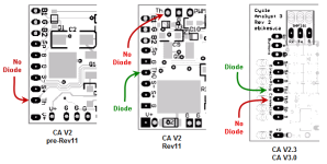
    As the OP mentioned, the diode arrangement and pad labeling varies depending on CA revision - it's important to get this right.
    • Select the diode input for Limiting mode operation (Large Screen CA V2 or V3)
      (What the OP describes...)
    • Select the 'no-diode' input for normal mode throttle control (CA V3)
    Here's a summary of the available throttle PCB pad designations:

    CAThrottleOutputByRev_2.png
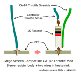
  • Current Limiting Resistor
    Although the OP was able to locate a series resistor in the PCB throttle circuit of that particular controller and hook to the opposite side, this is not always possible or convenient - particularly with more contemporary PCBs using tiny SMD devices. A more general alternative is to attach the current-limiting resistor directly in-line with the throttle input. The connection point is easily recognizable and requires minimal soldering skills. Here you remove the throttle wire, attach the throttle wire and CA wire to the resistor, optionally sleeve the resistor and wires in a piece of heatshrink, then insert the pre-wired resistor assembly into the PCB where the throttle was originally connected, solder, and trim the protruding excess resistor lead. The resistor current is trivial; choose a wattage for wiring robustness rather than electrical requirements - 1/4W or 1/2W have large gauge leads that can take a little abuse stuffing the PCB back into the case. This method works regardless of controller design.

    LargeScreenControllerThrottleMod4.png
  • Soldering to the Shunt
    Just a note here: It's best to solder the blue/white shunt connections to the shunt solder pad as close to the shunt as possible. Attaching to the shunt itself is possible, but the added wire wrap and solder will change the shunt value allowing the controller to supply higher current and requiring a re-calibration of the shunt because the shunt value on the controller label will no longer be correct. If you must attach to the shunt legs, squash the wire as close to the PCB as possible and don't splash solder up the shunt legs.

  • Generic Support without Opening the Controller

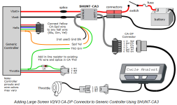
    An alternative solution is possible for those not wishing to modify the controller (warranty, soldering skills, etc). This approach yields identical operation and is detailed in the CA V3 Unofficial Guide in section "Appendix D. Adding a CA-DP Connector to a Generic Controller". The instructions apply to either large screen V2 or V3 operation. Here's the strategy - see the doc for more details:

    CA-genericController3.png
  • CA RShunt Calibration
    There are several means to calibrate the CA V2 or V2 shunt, some requiring instruments some not. For details, see "Appendix A. Calibrating the Cycle Analyst RShunt Value" of the V3 Guide.

A last note:
FWIW it's nice if you can just upload the photos to ES instead of linking to photobucket, etc. - particularly for HowTo works like this. We have gotten burned many many times by having linked photos disappear after a while, severely compromising the content and utility of the post. You have put a lot of effort into this and it would be good if it continued to have value years hence. ES photo posting can be a bit of a PITA for large or hires stuff, but...
Just a thought... :)
 
That's a KT controller. They normally use current control for the PAS, so each PAS level is a fixed current depending on which of the 5 levels you select. Therefore, if you use the PAS, you don't need any external current limit.
 
Hey guys,
Thanks for the additional info and diagrams. Great forum. Just discovered this site 2 weeks ago and it has helped me better understand so that this noob doesn't break anything. This stuff and site can be very technical, so will take it slow and stick with the KT display for now.. Thanks again!
 
Back
Top