connections for? EcityP Smart S5-13 BMS

I'm not sure that I can. It would take a few hours to draw out the smart board and exact components required. It's not my field so I would be using MSpaint. I could do it quicker with relays I guess... But optical isolation of the signal paths would be a lot better than mechanical isolation that could weld. I will give it 5 mins and see if I can get something together in principle. Don't hold your breathe :)
 
No bms provided short circuit or overload protection, but they can both disconnect a bulk charger or the load.

Very rushed job. It's nearly lunch here, My mind is elsewhere. I couldn't even draw two boards in series lol

Pick away at it please, It's how things get done :)

bms.jpg
 
Looking at the charging example above, We should have the two boards light an led rather than power a relay. Then we would power a small circuit from full pack voltage that watch's the two led's and if they are both lit, then we connect the charger with a semiconductor of some sort. This is optical isolation and tiny packages exist that contain the tx and rx leds and amplification. Making most of it already done for you.

The same applies for the output.

If you want the programmable current limitation returning too the output that can be done, but returning it too the charging circuit serves no purpose I can see. These boards watch voltage drop across the fets to judge current. I would let the bottom board control this. To do so, a couple of shunts in series would produce a voltage that can't go over half pack. It could be trimmed, and the board threashold programmed, so any current limit you wanted is possible. How to get this voltage to the chip I would have to look at, but I imagine there is a sensing pin just waiting for it.

This should put two boards in series with full functionality except for programming. This would have to be done a board at a time as the software will likely only support 13s and only one board is being used to control the output current regulation.


These boards offer a few unseen easter eggs. 3 channels for temperature monitoring each, leds for each balance channel and 5 leds that show charge level. All just need hooking up.

At $20 a board and not a lot more to pair them up, the programmable 26s that people keep asking for is here at the price they want without having to start from scratch. The design just needs a good polish.


I won't be doing any more with this as I just don't need one and all that really remains is the legwork of fetching other peoples work to the table. High power switching from the pre-charge threads and optoisolators from Vellaman or Farnel should be about it. The oz890 chip data for current control input. It is all just needs bringing together and writing up. I doubt anyone will though.


Edit: Be aware, I did electronics at school in the 80s. I'm reaching out here.
 
exco said:
altermontrealiste said:
what about using 2 of those bms's in series? Finding a bms that does 18s and 20s is hard...

thanks
Depends on what you want to do achieve.
You can do the balancing for 18/20s - maybe even LV/ HV / over current cutoff on the bms connected to the
lower half of your battery pack since that is done on the low side (fets cutoff minus).

I have no idea about what chemistry you are looking for - but e.g. 20S LiFePo4 are available.

Thanks exco ; I actually like the oz890 chip, especially for it's possibility to report battery details to an arduino, I have a 20s with konions and a 18s with chevy volt batts.

Is a dual oz890 bms available?
I'll try to contribute to designing and testing dual ecityp smart s5-13 bms
 
The batteries I use are big and overspected (I ride 500w e-bikes) ; LV can be managed by controller and it will not draw the 245A the pack is able to (it's fused at 60a) , charging voltage/amperage can be managed by my meanwells. I only want to ballance and report cell voltage like so :
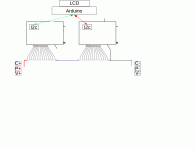
bms oz890 dual v0_1.gif

I understand I'll have to isolate both i2c to arduino, and other details not drawn here, but how minimalist can I make it? will the chips freak out without c-,c+, b-, b+ p+ and p-? what's the minimum to have the chips powered up?

can I use higher ohm resistors to bleed unballanced cells faster (more heat, I know)?

if I were to try make a pcb with 2x oz890 taken off bmsbattery's board, http://liionbms.com/php/wp_bms_chips.php says they are stackable up to 208, how would I stack them (and, most probably, reprogram them...)?
 
Ooo, I would like that circuit. Do you mean the one bmsb have for $100 most of the time? leads, software, basically provide my own desktop computer and I'm golden?

Itching to send you the money right away!
 
altermontrealiste said:
The batteries I use are big and overspected (I ride 500w e-bikes) ; LV can be managed by controller and it will not draw the 245A the pack is able to (it's fused at 60a) , charging voltage/amperage can be managed by my meanwells. I only want to ballance and report cell voltage like so :


I understand I'll have to isolate both i2c to arduino, and other details not drawn here, but how minimalist can I make it? will the chips freak out without c-,c+, b-, b+ p+ and p-? what's the minimum to have the chips powered up?

can I use higher ohm resistors to bleed unballanced cells faster (more heat, I know)?

if I were to try make a pcb with 2x oz890 taken off bmsbattery's board, http://liionbms.com/php/wp_bms_chips.php says they are stackable up to 208, how would I stack them (and, most probably, reprogram them...)?


b- and p+ will be needed to power the board. Remember, they must be connected before the balance plug, or it will smoke.

You could pop a resistor over the originals to increase balance current but they are not bad anyway. I can't think why you would make up new boards though.
 
friendly1uk said:
altermontrealiste said:
The batteries I use are big and overspected (I ride 500w e-bikes) ; LV can be managed by controller and it will not draw the 245A the pack is able to (it's fused at 60a) , charging voltage/amperage can be managed by my meanwells. I only want to ballance and report cell voltage like so :


I understand I'll have to isolate both i2c to arduino, and other details not drawn here, but how minimalist can I make it? will the chips freak out without c-,c+, b-, b+ p+ and p-? what's the minimum to have the chips powered up?

can I use higher ohm resistors to bleed unballanced cells faster (more heat, I know)?

if I were to try make a pcb with 2x oz890 taken off bmsbattery's board, http://liionbms.com/php/wp_bms_chips.php says they are stackable up to 208, how would I stack them (and, most probably, reprogram them...)?


b- and p+ will be needed to power the board. Remember, they must be connected before the balance plug, or it will smoke.

You could pop a resistor over the originals to increase balance current but they are not bad anyway. I can't think why you would make up new boards though.

thanks for the info :) ; I have a couple chevy volt packs that I would like to use at 18s, 24s or maybe 30s, and am thinking of building a battery analyst with sim-card theft-alarm and other features.
 
fo the adum1250: u just need one on the high side oz890. the low side one can talk at ground (or B-) level.

anyway, you can use the adum1250 also to get rid of ground noise from your CCCV powersupply. I had issues when monitoring while charging that went away when i connected the oz890 through that coupler.

Be aware that this coupler needs some mA of current. the oz890 should turn it off eventually, still i got a drained pack when not using it for some time. I did never check if the connected 3.3V load was the reason, i didnt investigate, but you have been warned. If you want to permanently connect this to your battery, check the current consumption of that circuit first. It should go to sleep mode after some minutes idling

for the unused pins: pull them to ground, except the unused cell ADCs, pull them to B+. The oz890 should behave normal if i didnt miss something
 
Hi,

has anyone successfully connected fuel gauge LEDs to this board?

I tried, and fried mine yesterday....

The spec sheet of the OZ890 says 'LED DRIVER'. So I thought that meant LED0-LED4 would give 2.1v or something, to drive a LED against ground. It did nothing. Measured, LED0-4 all gives 0.0 volts.

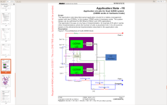
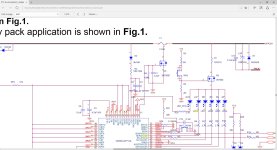
So then I found a schematic from the 'app notes' document, and after googling the LED symbol in page 16 (i am not an electronics guy), I figured the LED0 side was ground, and the other end of the LED should be connected to +. So i tried 3.3v, nothing happened. Tried VCC right next to it, thinking that would give 5v, BOOM lightning, I could even see sparks flying from the back of the board. I guess VCC=full pack voltage...


So, if anyone have made the LED0-LED4 work, please explain it like I'm five!
 

Attachments

  • Microsoft Edge 10.08.2016 21.52.04.jpg
    Microsoft Edge 10.08.2016 21.52.04.jpg
    200.9 KB · Views: 1,480
haha, that's funny :D when the smoke comes out, it stop's working. sure VCC is pack voltage. the oz890 das not need any low voltage power source, it is built-in. One of th reasons these boards are so cheap. Get another one.

The way you connect the LED cathode to the chip was right. But you cannot connect the anode to +3.3V. As stated in the datasheet, the 3.3V rail can only supply 10mA or so, one LED needs 20mA.

This is why you need to connect anode to VCC (or B+ Pack voltage), but with a 2.7k resistor in series to limit current through each LED. Just like it is shown in the schematic you posted. The tiny mosfet, FET and switch are there to switch on the LEDs, so they do not constantly glow and waste energy. You can simplify that: just connect it through a switch that can stand 100mA. Each 2.7k resistor eats around 1W when the LED is glowing, so if you use common 1/4 W resistor package, you should not press the button for too long ;)
 
Back
Top